There is only one source. R-2R ladder with low-pass filter at the end (Zout = 625 Ohm).
That's right, your DAC is to be hardwired to the headphone amp, I'd forgotten that. In that case, sure, remove C1 you don't need it.
One more thing. I'm toying with an idea of running the board at 18V. Besides replacing Zener diodes and Nichicon caps, is there anything else I should take care of?
I popped in Sparko Labs' SS3601 discrete op amps in place of the OPA134's. Theoretically a drop-in replacement, or so I thought. Disappointed! They are so far unlistenable. Output is down, and turning up the gain I'm getting noise over the music signal. Haven't done anything more than scratch my head and make sure the OPA134's work again in the circuits - and they do, perfectly.
I'm wondering if these little boards need to be shielded.
I'm wondering if these little boards need to be shielded.
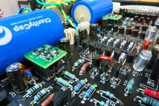
Attachments
The specification open loop gain of the SS3601 is 140dB to 600 Hz. According to the OPA134 data sheet, the 134 gain spec is 120dB. On completion of the boards, my test voltages were very close to expected values according to the build sheet. I probably have at least a couple hundred hours or more on the boards with the kit op amps.
Andrew says some circuits can create input bias current induced offsets with the
discrete devices. Tomorrow I’ll poke around with a meter and see what’s what.
Andrew says some circuits can create input bias current induced offsets with the
discrete devices. Tomorrow I’ll poke around with a meter and see what’s what.
Datasheet
Pretty standard stuff and no reason why it wouldn't work in this application. I suggest following the advice given in the datasheet and try adding 22 pF in parallel with the Sapphire feedback resistance R4. As you note, its also worth checking the DC offset at the op amp output pin 6 (should be <100 mV) to make sure nothing really odd is going on.
Loss of gain + distorted sound would seem to point to an ultrasonic instability. There may be other possibilities though I can't think of anything right off the top of my head.
Datasheet
Pretty standard stuff and no reason why it wouldn't work in this application. I suggest following the advice given in the datasheet and try adding 22 pF in parallel with the Sapphire feedback resistance R4. As you note, its also worth checking the DC offset at the op amp output pin 6 (should be <100 mV) to make sure nothing really odd is going on.
Loss of gain + distorted sound would seem to point to an ultrasonic instability. There may be other possibilities though I can't think of anything right off the top of my head.
I recall now that my DC offset on first power up with the OPA134 was 5mV on one side, 15mV on the other. I'll check it again before I put the SS3601's back in.
According to Sparkos' docs, the input capacitance is 5pf and stability starts getting compromised when the feedback resistance gets above 10K. Thus, as Richard stated, and Sparkos recommends, a 22pf across R4 is needed when R4 is larger than 10K.
The upper limit for the compensation capacitor Cf depends a little on the feedback resistance, for R4=22k is about 47 pF, R4=10k about 100 pF, R4=5k about 220 pF.
Much smaller than that and the effectiveness is compromised. Much larger and the audio frequency response suffers a treble cut.
Give it a shot anyway.
Much smaller than that and the effectiveness is compromised. Much larger and the audio frequency response suffers a treble cut.
Give it a shot anyway.
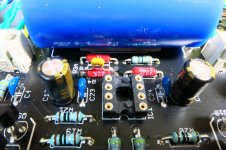
Discrete Op Amp voltage measurements
I had already soldered in 22pF caps by the time I saw your last post, Richard. My R4 is 22K, so I should be using a higher value. I did not take any measurements before putting the new caps in. I popped in the SS3601's and powered it up and it still sounds crappy, no change. With my DMM I measured V++ to V--, each channel is just a hair under 37V. Input offset is zero, both channels, but output offset is 9.6V, both channels. Yikes, it should be a few mV. Voltage across pins 4 and 7 is 21.24V (left), 21.14V (right).
I powered it off, pulled out the discretes and put the OPA134's into the sockets. Output offsets have settled right down to 3mV left and 18mV right. Voltage across pin 4 and pin 7 is 21V each side.
I am at a loss...
Attachments

9.6 V!? Slammed right up to V+ in other words. So, yeah, OK .. now we know what why it doesn't sound good, but what caused the op amp to do that?
We are looking at DC gain of 26 dB. (20x). So for +9.6 DC output the input offset (voltage difference between inv and noninv inputs) must be at least +500 mV.
Nothing I can see from the op amp module or the Sapphire circuit would induce that.
Anyone?
We are looking at DC gain of 26 dB. (20x). So for +9.6 DC output the input offset (voltage difference between inv and noninv inputs) must be at least +500 mV.
Nothing I can see from the op amp module or the Sapphire circuit would induce that.
Anyone?
Last edited:
Both SS3601 op amp boards produce the same output offset of 9.6 V. I keep wondering if I'm plugging these things in backwards or something. But that can't be, pin #1 is marked by the L-shape on the top corner.
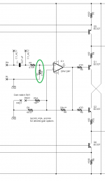
I suspect there may be an input bias current induced offset.
Looking at the schematic of the amplifier, the + input can only bias through a 47K resistor. The input bias current is around 5uA, so the input will see a DC offset of a couple hundred mV, amplified by the gain, it could be causing the offset.
You can try putting a 2.2M resistor or so from the + op amp input up to the +12V supply rail to supply the bias current. The value may need to be played with to get an acceptable offset.
Im assuming your offset is actually negative, correct? And are you measuring at the op amp output or the ouput of the entire amplifier?
Last edited:
I suspect there may be an input bias current induced offset. ...
Im assuming your offset is actually negative, correct? And are you measuring at the op amp output or the ouput of the entire amplifier?
I'm measuring at the amp output terminals, not at the op amp. As to whether its truly negative or not, I am not sure. I wasn't paying much attention to polarity, I was just alarmed at the magnitude of the reading. I'll have to put it back together and measure again.
Edit: Output offset appears to be negative for both the OPA134 (-5mV and -19mV) and the SS3601 (-9.64V and -9.61V).
Last edited:
Thanks Sparko for joining in.
I see now your module's input offset current is 4.5 uA typ. Compare that with the NE5534A's 10 nA and the problem comes into clear focus. With R2 47k or higher, anything over 50 nA is going to be a problem.
The workaround would be to add a 22uF capacitor between R3 and ground. This sets the DC gain to unity, lowering the output offset voltage back to value seen at the inputs.
That said, 4.5 uA is too high for this circuit application even then. I think it would be a good idea in addition to change the volume control to 10k, and reduce R2 to 10k to match. Only then will you get output voltages down into what I consider the "safe zone" of 50 mV or less.
4.5 uA x 10k x unity gain = 45 mV.
Take home: if your are going to use a discrete module for the Sapphire, JFET inputs will be a nice feature. Failing that, pay close attention to the input offset current and keep R2 and the volume control as low as impedance as possible.
Attachments
Last edited:
Yep, sounds like a classic example of trying to use an op-amp whose input bias current is too high.
Unfortunately, this is usually the case with a lot of the better sounding bipolar op-amps.
In addition, the higher the gain, the higher the offset. No surprise that you're getting 9V at the amp's outputs.
Any op-amp with a input bias current specification in micro-amps probably isn't going to work very well unless you can equalize the impedances "seen" by the + and - inputs.
Any op-amp with a input bias current specification in micro-amps probably isn't going to work very well unless you can equalize the impedances "seen" by the + and - inputs.
I'm borrowing this. Perfect phrasing.
Just finished it this morning. All good apart from a stuff up wiring the pot🙄
The pot is a 20k Alps I had. I'm not sure if the MS Audio pot on ebay will fit. Not sure if the Valab version is worth it either.
It sounds great running through the headphone out of my pad playing Pandora. Will close it up and move it over to the rack.
The gain switch is on the underside and works fine. I might try and get better plugs or just solder the wires to the pins. The switch is just friction fixed so far. It needs tiny holes and screws but I may just glue it on.
The caps are Obligato - thought I might as well get them as I bought the gain resistors from DIYhifisupply.
Thanks RJM - another happy repeat customer.
kffern
An externally hosted image should be here but it was not working when we last tested it.
An externally hosted image should be here but it was not working when we last tested it.
- Home
- Amplifiers
- Headphone Systems
- RJM Audio Sapphire Desktop Headphone Amplifier