check all source resistors , confirm that you have +/- voltage at pcb (so , that would be +22/-22 , for instance)
post here
post here
confirm both positive and negative supply on pcb
then leave just one pair of output mosfets connected , then check functionality
then leave just one pair of output mosfets connected , then check functionality
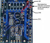
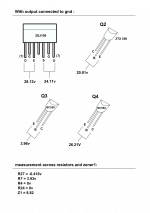
Hi ZM, I've got 46.6v on the + and - on the board. I'd removed all the mosfets except the ones on Q5 and Q7. But on Peter Daniel's board, the R13 is connected to the Q8 instead of the Q7.
On the underside of the board, you can see the connection from the R13 to the R19 and thus, connecting it to the Q8.
Attachments
Last edited:
I have a 22v secondaries but only 150 VA transformer. Do you think I can test it on the Aleph J?
you lost me there ........
I insisted on confirming +/- PSU voltage on amp pcb , as a way to confirm both PSU functionality and GND existence on amp pcb itself
regarding leaving just one pair of mosfets connected for tests - that's way of simplifying things - and leave connected just ones necessary for proper amp functionality ; as I'm not having direct experience with PD pcbs , I can't be certain which position(s) of output mosfets is crucial , without enclosed both ref. schematic and decent pcb pictures
so - what to do first ......... disconnect all (output mosfet's) source resistors ( lift one resistor end from pcb .... or desolder source wire -probably easier in your case) ; that way all mosfets are out of circuit , so we can check functionality of input side .
gnd both inputs .
power amp on - check functionality of input LTP - that means - measure all important nodes of input LTP CCS , and voltage across input JFet drain resistor
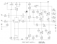
please attach (or link to ) ref. schematic with results
if you do that - I can write exactly what and how to measure
then we can proceed
I insisted on confirming +/- PSU voltage on amp pcb , as a way to confirm both PSU functionality and GND existence on amp pcb itself
regarding leaving just one pair of mosfets connected for tests - that's way of simplifying things - and leave connected just ones necessary for proper amp functionality ; as I'm not having direct experience with PD pcbs , I can't be certain which position(s) of output mosfets is crucial , without enclosed both ref. schematic and decent pcb pictures
so - what to do first ......... disconnect all (output mosfet's) source resistors ( lift one resistor end from pcb .... or desolder source wire -probably easier in your case) ; that way all mosfets are out of circuit , so we can check functionality of input side .
gnd both inputs .
power amp on - check functionality of input LTP - that means - measure all important nodes of input LTP CCS , and voltage across input JFet drain resistor
please attach (or link to ) ref. schematic with results
if you do that - I can write exactly what and how to measure
then we can proceed
Last edited:
with mosfet outputs still out of circuit - conect amp's output to gnd ( to establish gnd for Q1B gate ) and repeat measurements
please - use notes as "across" resistor when measuring across it
for voltages referenced to gnd , specify exact node
please - use notes as "across" resistor when measuring across it
for voltages referenced to gnd , specify exact node
it seems everything is ok
remove bridge from output to gnd , put one pair of (checked!) mosfets in place and power it up
report here
when you have functional amp with one pair , you'll put second one
remove bridge from output to gnd , put one pair of (checked!) mosfets in place and power it up
report here
when you have functional amp with one pair , you'll put second one
Thanks ZM. Should I disconnect the input from the ground as well? I also noticed that the board vibrates when it's powered up and the transformer buzzes.
Thanks ZM. Should I disconnect the input from the ground as well?.......
all the time - until it's ready to sing
T...... I also noticed that the board vibrates when it's powered up and the transformer buzzes.
??!
with or without mosfets in circuit ?
even if I can't see anything wrong on your pictures , you're th eone who need to check every connection
insert Ampermeter in each rail (one by one ) , between cap bank and pcb and measure - without mosfets you'll have up to 20-30mA , no more
with mosfets - increased for Iq
all the time - until it's ready to sing
??!
with or without mosfets in circuit ?
even if I can't see anything wrong on your pictures , you're th eone who need to check every connection
insert Ampermeter in each rail (one by one ) , between cap bank and pcb and measure - without mosfets you'll have up to 20-30mA , no more
with mosfets - increased for Iq
Hi ZM. You mean ground the inputs all the time until it is ready to sing?
The board vibrates with and without the mosfets connected. It wasn't there before.
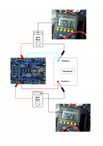
So, one probe on the negative rail and one probe on the negative of the amp board pcb to test the ampere and then repeat the same for the positive rail, is this correct?
Hi ZM. You mean ground the inputs all the time until it is ready to sing?
yup
........
The board vibrates with and without the mosfets connected. It wasn't there before.
....
that's confusing .......
..........
So, one probe on the negative rail and one probe on the negative of the amp board pcb to test the ampere and then repeat the same for the positive rail, is this correct?
yup
find some tutorial on web , how to make basic measurements
look here , for instance :Basic Car Audio Electronics
look at right menu - Digital Multimeter
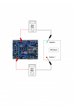
you mean - one pcb is drawing 0,54mA from pos and and 0.21mA from neg rail ?
with JFets in place , just mosfets removed from circuit ?
as I said :
with JFets in place , just mosfets removed from circuit ?
as I said :
.......
insert Ampermeter in each rail (one by one ) , between cap bank and pcb and measure - without mosfets you'll have up to 20-30mA , no more
with mosfets - increased for Iq
you mean - one pcb is drawing 0,54mA from pos and and 0.21mA from neg rail ?
Yes, please see attached picture on how I took the measurement.
with JFets in place , just mosfets removed from circuit ?
Yes, with JFets in place and mosfets removed from the circuit.
as I said :
Should I take the measurement as in picture 'fets measurement.png4'?
Thanks, ZM.
Attachments
- Status
- Not open for further replies.
- Home
- Amplifiers
- Pass Labs
- Rising DC Offset