Thanks, ZM.
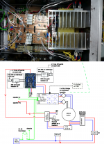
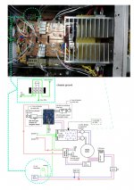
This is how it is setup. I think I have connected Peter Daniel's board SG signal erroneously to the XLR pin 1. I always heard a faint buzzing sound on my speaker. What component would be damaged by this?
I think it's correct, it's the ground signal.
Thanks.
This is how it is setup. I think I have connected Peter Daniel's board SG signal erroneously to the XLR pin 1. I always heard a faint buzzing sound on my speaker. What component would be damaged by this?
I think it's correct, it's the ground signal.
Thanks.
Attachments
Last edited:
I can't see nothing wrong
be sure that all mosfets are tightly fixed , measure temperature of all of them (mid pin is right place for probe) to be sure
be sure that all mosfets are tightly fixed , measure temperature of all of them (mid pin is right place for probe) to be sure
if mosfet is nailed , it demands replacing
so - if dead amp isn't bothering you , who am I to argue ?

“The test of the machine is the satisfaction it gives you. There isn't any other test. If the machine produces tranquility it's right. If it disturbs you it's wrong until either the machine or your mind is changed.”
― Robert M. Pirsig, Zen and the Art of Motorcycle Maintenance: An Inquiry Into Values
so - if dead amp isn't bothering you , who am I to argue ?
Post42
The third wire of the Mains cable must be bolted to the Chassis !!
The earth wire is connected to the chassis.
I've replaced the mosfets and install a light tester to the mains and when I powered up the amp, the 40w light bulb lights up. Something is wrong.
Attachments

Last edited:
if amp is fully biased , and Aleph J is by construction (not starting biasing procedure from zero as , say, F5) - bulb tester can be used 😱nly: for testing of unloaded PSU
so - fit appropriate fuse in mains , one dvm for observing Iq , another one for output offset ........ and bang it on
under condition that you triple checked everything in cold
so - fit appropriate fuse in mains , one dvm for observing Iq , another one for output offset ........ and bang it on
under condition that you triple checked everything in cold
The earth wire is connected to the chassis.
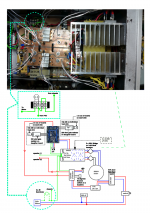
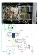
post42 shows the Audio Ground connected to Chassis.
The Mains PE wire is not shown connected to Chassis.
Who are you trying to kill?
post42 shows the Audio Ground connected to Chassis.
The Mains PE wire is not shown connected to Chassis.
Who are you trying to kill?
Hi Andrew,
I have connected it this way as shown in the diagram.
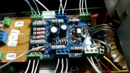
I ve powered up the amp without the light tester and it seems to work! DC offset is at 50mV when switched on and drop to 39mV after an hour. R7 is at 4.8v and Z1 is at 8.8v. But the mosfets are not well matched.
Attachments
Hi Andrew, Isn't the chassis connected to the mains ground along with the star ground? If not, how is it to be done?
The third wire in the mains cable must be fixed/bolted to the Chassis. This is your Protective Earth (Safety earth).
There are no alternatives.
You MUST make the Chassis safe.
There are no alternatives.
You MUST make the Chassis safe.
The third wire in the mains cable must be fixed/bolted to the Chassis. This is your Protective Earth (Safety earth).
There are no alternatives.
You MUST make the Chassis safe.
Hi Andrew,
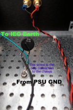
It is bolted to the chassis and then connected to the CL40 thermistor along with the star ground from the PSU.
The measurement as in the attached picture.
Attachments
You are still showing the PE wire connected to the Thermistor.
That is wrong and potentially dangerous.
That is wrong and potentially dangerous.
Shouldn't the chassis connect to the thermistor? If not, then the drawing in post #53 should be correct. The attached picture is from 'Aleph J illustrated build guide' post #1.
Attachments
Last edited:
Connect the PE wire to Chassis.
Do that and get the Safety Earth right.
Hi Andrew, you mean as in post #53 and by passed the thermistor? Thanks.
- Status
- Not open for further replies.
- Home
- Amplifiers
- Pass Labs
- Rising DC Offset