Consider investing in a differential probe (you are trying to measure a very high-speed signal ~400MHz), then you can measure these high frequency / low amplitude signals around the circuit even if neither "side" is grounded; i.e. the fact that the oscilloscope is grounded won't matter.
I checked the schematics.... the clock assembly feeds clock signal to 3 different destinations; 2 are unbuffered; one is buffered. Which one are you trying to measure?
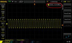
To fit more cycles of a signal on the LCD (for example 30, as suggested...), adjust the time base.
Does the oscilloscope power cord have an earth pin? Also, are you sure that the mains (IEC) connecter earth pin at the back of the oscilloscope is DC (directly) coupled to the probes' BNC connector shell? Very unlikely! The mains ground is properly connected to the BNC ground using capacitors (of various capacitance).
Also, always use the probe's setting of 10:1.
I checked the schematics.... the clock assembly feeds clock signal to 3 different destinations; 2 are unbuffered; one is buffered. Which one are you trying to measure?
To fit more cycles of a signal on the LCD (for example 30, as suggested...), adjust the time base.
Does the oscilloscope power cord have an earth pin? Also, are you sure that the mains (IEC) connecter earth pin at the back of the oscilloscope is DC (directly) coupled to the probes' BNC connector shell? Very unlikely! The mains ground is properly connected to the BNC ground using capacitors (of various capacitance).
Also, always use the probe's setting of 10:1.
If you plan to use your scope in a variety of amplifier measurement a isolation transformer is a good safety measure.
Bill
Bill
Yes, adjust the time base - the horizontal time / division control - until there's more cycles on the screen.
Since you're just measuring frequency, you may get away with a cap between the scope probe ground and the ground at the measurement point. Big enough cap to let 4MHz through, small enough to reject the AC interference.
You may get away with using a ground pin isolator on the scope AC cord. This advice requires caution - Tektronix screamed bloody murder about their scopes not being earth grounded, yet they designed them to be able to do so (even their battery powered scopes had all kind of WARNING about not connecting the scope ground to earth ground) Unsure if Rigol can do this...
You might power the Rigol with a 12V battery and a small AC inverter; that would float it.
I've never seen an AC isolation transformer where the AC ground isnt simply passed through to the secondary sockets. No one in their right mind is going to manufacture something that does otherwise - you'd have to DIY customize such a device, which I think may be beyond your "scope". Be DAMN careful around AC line stuff...
I have a 20MHz Fluke 123 scope which would make this measurement - fully isolated, battery powered.
Yes, adjust the time base - the horizontal time / division control - until there's more cycles on the screen.
Since you're just measuring frequency, you may get away with a cap between the scope probe ground and the ground at the measurement point. Big enough cap to let 4MHz through, small enough to reject the AC interference.
You may get away with using a ground pin isolator on the scope AC cord. This advice requires caution - Tektronix screamed bloody murder about their scopes not being earth grounded, yet they designed them to be able to do so (even their battery powered scopes had all kind of WARNING about not connecting the scope ground to earth ground) Unsure if Rigol can do this...
You might power the Rigol with a 12V battery and a small AC inverter; that would float it.
I've never seen an AC isolation transformer where the AC ground isnt simply passed through to the secondary sockets. No one in their right mind is going to manufacture something that does otherwise - you'd have to DIY customize such a device, which I think may be beyond your "scope". Be DAMN careful around AC line stuff...
I have a 20MHz Fluke 123 scope which would make this measurement - fully isolated, battery powered.
Hold on a sec doesnt a cap block DC and let AC through?
I have the same scope: use the counter function! The frequency display works better if you have some 10 to 20 waves in the screen: if you have only 3 waves displayed it can't calculate of course an exact value!!
Last edited:
If it is a dual channel scope do a subtract between the channels. Grounds to the chassis somewhere and the two probes across the signal of interest. This is much cheaper than buying a differential probe.
As mentioned in this thread: use settings for averaging, noise reduction etc. etc.!
Attachments
Last edited:
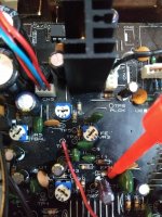
Hi, the cable is to ground the resister as per instructions. When I do ground it I get a lot of noise. 😱
I suspect they didn't mean chassis ground. You will need to identify a local ground on the board. Possibly there is a something identified as a ground point on the board itself.
The chassis safety GND may not be connected directly to the board GND plane.
Possibly use the same point the RCA output jacks connect to, although technically that is probably too far away even at 4.3MHz.
The chassis safety GND may not be connected directly to the board GND plane.
Possibly use the same point the RCA output jacks connect to, although technically that is probably too far away even at 4.3MHz.
A quick hint as to whether the PCB ground and safety ground are connected would be to measure the DC resistance between chassis and the RCA jacks using a DMM.
- Home
- Source & Line
- Digital Source
- Rigol DS1054Z not stable reading MHZ