Low levels of grid current are seen with all valves. This normally can be ignored, but it is a noise source so may need to be taken into account for low noise circuits. At the very least its contribution should be estimated, in order to justify ignoring it.fdegrove said:Under normal circumstances and assuming a non-leaky valve no grid current should occur with a correctly biased triode. If it does then you're dealing with al leaky valve and it should be replaced.
Hi,
That formula is only valid for applications well above the LF band. For AF it is pretty much useless.
Ciao, 😉
Please provide a reference. Otherwise, I think you're just repeating what others have told you. I don't believe the formula is useless at audio frequencies. It's just not the whole picture, as I said. There is a formula for the total noise, but I can't find it now.
On my website I found the formula which can be written as Ns/Np = sqrt(Req Rin)/Rs. Rin is the effective input impedance of the valve, and can consist of bias resistor, transformer losses (transformed to a parallel form), valve grid impedance etc.
If we take a wild stab at Rin = 1M, then Req=200 and Rs=200 gives Ns/Np = 70.7 for optimum noise. The idea is that the source noise (multiplied by the transformer ratio), input resistance noise (loaded by the transformed source impedance) and valve noise are all equal. If the input resistance is dominated by the valve itself (unlikely at audio frequencies) then a smaller ratio is needed to get more loading, as the effective temperature of the input resistance is higher than the others.
So, you claim to know more about this than Walt Jung?
Low levels of grid current are seen with all valves. This normally can be ignored, but it is a noise source so may need to be taken into account for low noise circuits. At the very least its contribution should be estimated, in order to justify ignoring it.
He has 1 volt of bias on the input tube. There isn't any significant grid current, assuming it is a good tube with high vacuum.
I'm not a member so I cannot read the full article.
to Walter, the PC card is not poor. It is semi-professional E-MU 0404 PCI. Its characteristics are faaar better that my preamp will be. However its input is unbalanced, that is why output of the preamp is not balanced. BTW, and I think it is more important, the input of preamp is balanced with help of SUT.
to DF96, there is a point. I am learning. Nobody was born with this type of knowledge pre-wired in head. Everyone got that by learning. Thank you for helping me.
to dirkwright, my understanding is that load on the SUT secondary should be as low as possible. Transformer can be imagined as a lever with a hinge placed at ratio. So if we put even small load on long shoulder, it will create big load on short one. This means load on secondary it will make big resistance to ribbon connected to primary. It will dump the ribbon and make sound tinny. Ribbon is driven just by acoustic energy which is not that high, so task is to transform its weak mechanical oscillations into electrical ones with as big as possible amplitude (V~). That is why transformer(s) are here. That is why I use tubes, because of their virtually infinite input impedance. I think due to all kinds of natural losses and embedded resistances there is already enough load on secondary. For example, increasing ratio of LL1935 from 1:5 to 1:10 causes causes audible rolloff at LF and HF, though increases Vin.
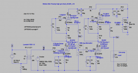
R8 is for simulator, does not exist in reality. I also doubt in R6. Though I do not think it can produce too much noise with virtually no current through it. I'll remove it anyway.
C1 is to kill RF. I'll try to remove it because anyway I use ferrite beads on grids (and other pins too).
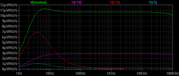
I also reduced currents through both stages. Here is new schematic.
According to noise analysis in LTSpice (second picture), the biggest contributor of LF noise (in 1Hz..1kHz band with big hump 2.1uV/Hz^1/2 on 10Hz) is R14.
Second contributor is R18 grid stopper. Should I remove this one too?
to DF96, there is a point. I am learning. Nobody was born with this type of knowledge pre-wired in head. Everyone got that by learning. Thank you for helping me.
to dirkwright, my understanding is that load on the SUT secondary should be as low as possible. Transformer can be imagined as a lever with a hinge placed at ratio. So if we put even small load on long shoulder, it will create big load on short one. This means load on secondary it will make big resistance to ribbon connected to primary. It will dump the ribbon and make sound tinny. Ribbon is driven just by acoustic energy which is not that high, so task is to transform its weak mechanical oscillations into electrical ones with as big as possible amplitude (V~). That is why transformer(s) are here. That is why I use tubes, because of their virtually infinite input impedance. I think due to all kinds of natural losses and embedded resistances there is already enough load on secondary. For example, increasing ratio of LL1935 from 1:5 to 1:10 causes causes audible rolloff at LF and HF, though increases Vin.
R8 is for simulator, does not exist in reality. I also doubt in R6. Though I do not think it can produce too much noise with virtually no current through it. I'll remove it anyway.
C1 is to kill RF. I'll try to remove it because anyway I use ferrite beads on grids (and other pins too).
I also reduced currents through both stages. Here is new schematic.
According to noise analysis in LTSpice (second picture), the biggest contributor of LF noise (in 1Hz..1kHz band with big hump 2.1uV/Hz^1/2 on 10Hz) is R14.
Second contributor is R18 grid stopper. Should I remove this one too?
Attachments
We are speaking about the noise when this project is not properly designed.
With these types of signal so low I don't suggest the use of tubes a first stage.
The use of Fet with a very very low noise figure is the first choice. No other chance.
In addition the idea to put two transformers in chain is out of every good technical reason first of all for the impedance related.
Again, the non use of balanced circuit is very dangerous for common mode current.
Bye
W
MM7,
I think that the idea to made a circuit must be absolutely compared with the use I have to do.
If you have a commercial audio card maybe will be better to use a simply circuit with Fet where the power comes from a pair of battery, p.e. 12 V /2A so you can reach a very good amplification with a lot of dinamics and you can leave the noise very low; with this solution you are also far for the common mode current issues.
Bye
W
Then how they made amps with quite good sound in 1930-50-es? Without FETs, without low noise MF resistors, with poor electro caps?With these types of signal so low I don't suggest the use of tubes a first stage.
The use of Fet with a very very low noise figure is the first choice. No other chance.
I understand that with tubes noise is not avoidable. I am trying to minimize it.
I am reading about starved mode for input stage.
http://www.valvewizard.co.uk/Triodes_at_low_voltages_Blencowe.pdf
Would this approach help? Does anyone has experience with it?
Hi,
Well, I do have about 27 years of experience with it. I've been using that topology as a MC input stage to avoid using a SUT.
Which is also why I sent you to the last 6 or 7 pages of the Itch phono thread where I hope to have provided enough information on how to use that topology and a number of tricks to reduce valve noise.
Ciao, 😉
Would this approach help? Does anyone has experience with it?
Well, I do have about 27 years of experience with it. I've been using that topology as a MC input stage to avoid using a SUT.
Which is also why I sent you to the last 6 or 7 pages of the Itch phono thread where I hope to have provided enough information on how to use that topology and a number of tricks to reduce valve noise.
Ciao, 😉
Last edited:
I make no claim about Jung. I applied circuit theory to a valve input. What did he do? If my analysis has a flaw then I would be pleased to hear about it so I can correct my thinking and website. You yourself admitted that the result you obtained (using his formula?) seemed wrong.dirkwright said:So, you claim to know more about this than Walt Jung?
There is an analogous analysis in a book by deMaw, dealing with RF JFET inputs, where he says that the input voltage step up can be increased almost without limit to get very good noise figures as the JFET has very high gate impedance - this is consistent with my result.
Thanks Frank, I keep reading...Well, I do have about 27 years of experience with it. I've been using that topology as a MC input stage to avoid using a SUT.
Which is also why I sent you to the last 6 or 7 pages of the Itch phono thread where I hope to have provided enough information on how to use that topology and a number of tricks to reduce valve noise.
Sorry, I'm late to this but could someone clarify.
Is that 60dB SPL or what is the reference? 60dB SNR re 60dB SPL would be overkill IMO, that makes the preamp noise at around 0dB SPL. 12dB is very quiet and 20dB quite acceptible.
Even worse. 30uV is after 1:37. Ribbon itself produces 1-2uV at 60dB volume.
Is that 60dB SPL or what is the reference? 60dB SNR re 60dB SPL would be overkill IMO, that makes the preamp noise at around 0dB SPL. 12dB is very quiet and 20dB quite acceptible.
The use of two series transformers is actually essential. Don't let anybody tell ya different. You can't easily afford the Ohmic losses without a transformer near the ribbon, and you can't easily afford the capacitive loading without a transformer near the first stage of electronics. In between is (roughly) standard mic level. That's also the way it's always been done, for good reasons.
All good fortune,
Chris
All good fortune,
Chris
Hi,
Agreed. Point is though that it have to be the right xformers for the job and not something picked out of a catalogue willy nilly.
Ciao, 😉
The use of two series transformers is actually essential
Agreed. Point is though that it have to be the right xformers for the job and not something picked out of a catalogue willy nilly.
Ciao, 😉
I've contacted Per Lundahl specifically for this question. It was his advise to use LL1935 because it fits impedances the best in my specific case.Hi,
Agreed. Point is though that it have to be the right xformers for the job and not something picked out of a catalogue willy nilly.
Ciao, 😉
I make no claim about Jung. I applied circuit theory to a valve input. What did he do? If my analysis has a flaw then I would be pleased to hear about it so I can correct my thinking and website. You yourself admitted that the result you obtained (using his formula?) seemed wrong.
There is an analogous analysis in a book by deMaw, dealing with RF JFET inputs, where he says that the input voltage step up can be increased almost without limit to get very good noise figures as the JFET has very high gate impedance - this is consistent with my result.
See chapter 6 of his book "Op Amp Applications", specifically pages 6.5 and 6.6. His equations are not specific to op amps.
I've contacted Per Lundahl specifically for this question. It was his advise to use LL1935 because it fits impedances the best in my specific case.
OK, then you should do just that regardless of what people here tell you.
I just did a rough estimate of the equivalent noise resistance of the input tube, so assuming it is much higher than I calculated, a 1:5 transformer is probably fine.
Hi,
Well, I do have about 27 years of experience with it. I've been using that topology as a MC input stage to avoid using a SUT.
Which is also why I sent you to the last 6 or 7 pages of the Itch phono thread where I hope to have provided enough information on how to use that topology and a number of tricks to reduce valve noise.
Ciao, 😉
A moving coil cartridge is not even close to the same kind of source as the ribbon microphone he is using. The microphone has a high step up transformer built into it, for example. I do not understand your aversion to input transformers, but that's your particular bias.
- Status
- Not open for further replies.
- Home
- Amplifiers
- Tubes / Valves
- Ribbon Microphone Preamp