Using a motor run cap in the first position is a waste (IMO). The only cap you are actually hearing is the last one so put your MRC there and find a compact electro for the first position. The last cap can have a prefound effect on the final sound, but even a simple small value bypass of an electro will produce that.
Shoog
Shoog
Shoog:
Thanks for that; I actually just stumbled on two other threads talking about motor run caps in the Tubelab Simple SE (my first build) saying the same thing. Thanks for the reinforcement.
Can you shed any light on my question about the 47uf cap and my 5v4g rectifier? Will that large of a cap stress my rectifier?
Also, I did a little more research on that last cap, and I keep finding recommendations that say "the more capacitance, the better" (at least in that position). Is the 220uf/bypassed with the small cap recommended in the schematic an average value for this position? On the low side? More than I need?
I would be inclined to think that 47uf may just stress your vintage rectifiers. The datasheet should be your final guide here. This is from the vintage when 8uf was a reasonable amount of capacitance in power supplies. This is why old amp tend to use chokes because they were cheaper than caps back then !!
I would give them an easy life and use 10uf, and simm it in PSU2.
In the final position, if you have included a big enough choke then just about anything goes. 220uf should be adequate but I would be inclined to go higher.
Shoog
I would give them an easy life and use 10uf, and simm it in PSU2.
In the final position, if you have included a big enough choke then just about anything goes. 220uf should be adequate but I would be inclined to go higher.
Shoog
Well wouldn't you know it, it says right there in the spec sheet, 10uf. I thought I had already been through that thing with a fine toothed comb.
I'll give that PSU2 a try.
Thanks again.
I'll give that PSU2 a try.
Thanks again.
Hey Shoog,
No secret the RH is wrongly designed. I know you have worked a lot with 6AU6 so probably you know best about it´s sweetspot🙂. Anyway this is what I would do. Only componentvalues differ.
what's wrong with an EL84 driving EL84 schaded? the tubes are cheap. Is it merely a question of overkill ?
Last edited:
Just another opinion:
I'd go for a slightly bigger filter input cap (20-22uF) - IMO this is a good trade between ripple and rectifier life. And I would really use a PP cap (e.g. motor run) in this position, not for the sonics, but for reliability: the input cap has a hard life too - surges and high ripple won't make an electrolytic happy, especially the cheaper one.
For the filter output cap I'd go for 470uF; or you can even use separate chokes - those Hammond 156Ls (5H, 75mA, 135Ohm DCR) are not that expensive, have a pretty low DCR and together with (separate again) 2x220uF caps will provide all the needed filtering and a better channel separation.
BTW, I don't think that TS-HAs need bypassing - they're quite good by themselves.
I am in the process of building a RH807 using the original circuit diagram.
However I am using 2 ECC81’s and 2 sockets to allow the use of pentode drivers without major modifications to the chassis.
As the implementation of a pentode driver is being discussed in this thread it provides an opportunity to obtain a suitable design. I have no experience in amplifier design and I am therefore looking for any help and guidance.
Shoog, Lars you seem to the main advocates for the pentode, I hope you can spare a few moments to assist.
I appreciate your position ‘the only way to learn is have a go yourself’ with that in mind I up with the following.
To allow the tube to swing the +/- 2V for Line Input the cathode will need to be in the range - 2.25- 2.75 V. B+ for the RH807 is 350V.
Option 1.
B+ 350V
Plate 200V .005A
g2 150V .0012A
feedback .001A
Ra 43k
Vg 2.25V
Option 2.
B+ 350V
Plate 250V .005A
g2 150V .0012A
feedback .001A
Ra 25k
Vg 2.25V
Option 3.
B+ 350V
Plate 250V .0076A
g2 150V .003A
feedback .001A
Ra 15k
Vg 2.25V
I plotted Vg (-2 to +2) against Pv & Pa for the options above and also Shoogs recommendations for the RH84.
I found that option 2 the most linier, reasonable –2 to +1.
However at +2 the Pv=340V which is above the max Pv of 330V.
Can someone please comment on the above, are the findings correct, or have I got it completely wrong, what would you recommend as an operating point.
Bear in mind that in Schade circuits, when you change the value of the plate resistor the value of the feedback resistor must be changed accordingly to maintain the same feedback ratio. A good rule of thumb is to make Rfb = 5Ra. This will get you into the right ballpark for further experimentation.😉
A good rule of thumb is to make Rfb = 5Ra.
Thanks mach1
Feedback ratio for the various designs,
Standard RH84 100k/22k = 4.55
Shoog RH84 100k/25k = 4.00
Revintage RH84 100k/15k = 6.67
Standard RH807 100k/33k = 3.03
Maintaining Pa at 0.005A and Pv at 250V.
The values of the Plate and Feedback resisters can be adjusted to give a feed back ratio of 3, 4 or 5 etc.
From my calculations the Load Line is not effected, the Plate Current (with no voltage over the valve) was determined by HT/Ra + HT/Fba.
If this is correct, is the optimum feedback ratio determined by listening.
The standard RH807 uses a ratio of 3, was this value also used by builders of pentode RH807 amplifiers or is there a better ratio.
John
I think you may try to aim for an effective feedback ratio of about 1:10
(as suggested by Schade for 6L6).
With a triode driver the internal plate resistance is a significant factor. With 12AT7 it is 10-15K, which will be in parallel with the plate resistor and the output grid-leak.
Your examples probably end up with about the 1:10 ratio - depending on the value you chose to assume for the drivers plate resistance.
With a pentode driver the internal resistance is very high, and can almost be ignored.
--
SB
Last edited:
Calling the ratio of the load resistor to feedback resistor the "feedback ratio" doesn't tell you the actual NFB ratio of the amplifier, because it ignores the transconductance of the output tube and it's in-circuit voltage gain.
In Schade's paper, he described a voltage divider feedback network which does set the NFB ratio, but in the RH type circuit the feedback comes from the balancing of the current through the feedback resistor against the current through the driver device (V/I converter). One might think of the feedback resistor being a V/I converter balanced against the input V/I converter giving the amplifier an overall v => i => V function with power gain.
One actually wants to know what fraction of the driver's signal current is seen through the feedback resistor. To estimate this I calculate Rfl (feedback load seen by the driver anode) as [Rfb * (gm * Za)] which accounts for the loaded voltage gain of the output tube (gm * the anode load impedance). Thus the actual feedback ratio is Rfl/(Rfl + Rl) where Rl is the load resistance || Ri of the driver.
When the feedback ratio is 1, e.g. with no driver load resistor or CCS, the effective plate impedance at the output anode is 1/gm. One may factor in other feedback ratios appropriately.
Triode vs. pentode vs. FET as a V/I driver?
Triodes are "linear" wrt voltage swing when unloaded because there is a region in which the triode's internal resistance changes appropriately with changing plate voltage to counteract the fundamental nonlinear characteristic. Kind of like an internal version of "Schade" feedback.
Pentodes are basically nonlinear but there can be found a more linear region over a particular voltage swing. Cathode degeneration helps, e.g. selecting a high-gm pentode and adding an unbypassed Rk. (The FET simply has a high gfs and can be degenerated a lot, as well as having it's own sweet spot)
Strange as it may seem, there are triodes that have fairly linear V/I relationships over a particular plate load and voltage swing. It's what makes a cascode circuit work well. I've plotted a few triode V/I load lines that look better than some of the pentode ones. Cathode degeneration can help with triodes also.
One advantage in using a triode or a FET as a driver is no screen grid circuit😛
Last edited:
Calling the ratio of the load resistor to feedback resistor the "feedback ratio" doesn't tell you the actual NFB ratio of the amplifier, because it ignores the transconductance of the output tube and it's in-circuit voltage gain.
In Schade's paper, he described a voltage divider feedback network which does set the NFB ratio, but in the RH type circuit the feedback comes from the balancing of the current through the feedback resistor against the current through the driver device (I/V converter). One might think of the feedback resistor being a V/I converter balanced against the input I/V converter giving the amplifier an overall v => i => V function with power gain.
One actually wants to know what fraction of the driver's signal current is seen through the feedback resistor. To estimate this I calculate Rfl (feedback load seen by the driver anode) as [Rfb * (gm * Za)] which accounts for the loaded voltage gain of the output tube (gm * the anode load impedance). Thus the actual feedback ratio is Rfl/(Rfl + Rl) where Rl is the load resistance || Ri of the driver.
When the feedback ratio is 1, e.g. with no driver load resistor or CCS, the effective plate impedance at the output anode is 1/gm. One may factor in other feedback ratios appropriately.
Triode vs. pentode vs. FET as a V/I driver?
Triodes are "linear" wrt voltage swing when unloaded because there is a region in which the triode's internal resistance changes appropriately with changing plate voltage to counteract the fundamental nonlinear characteristic. Kind of like an internal version of "Schade" feedback.
Pentodes are basically nonlinear but there can be found a more linear region over a particular voltage swing. Cathode degeneration helps, e.g. selecting a high-gm pentode and adding an unbypassed Rk. (The FET simply has a high gfs and can be degenerated a lot, as well as having it's own sweet spot)
Strange as it may seem, there are triodes that have fairly linear V/I relationships over a particular plate load and voltage swing. It's what makes a cascode circuit work well. I've plotted a few triode V/I load lines that look better than some of the pentode ones. Cathode degeneration can help with triodes also.
One advantage in using a triode or a FET as a driver is no screen grid circuit😛
Sorry Michael, I can't see the reason why the voltage divider approach to the calculation of feedback ratio outlined by Schade doesn't apply to the RH84. Can you please explain further.🙂
Sorry Michael, I can't see the reason why the voltage divider approach to the calculation of feedback ratio outlined by Schade doesn't apply to the RH84. Can you please explain further.🙂
OK, first, post 51 is correct and post 52 somehow got duplicated without edits...
One needs to think about the differences in circuit operation to grok this:
Schade's circuit and formulae on page 177 of the 1938 RCA journal are for a case where the output feedback is first divided, then summed with the driver signal. The driver signal is in series with the divided feedback. The two resistors of the divider set a simple feedback ratio.
In the RH circuit, and in my own embodiments of this technique, the driver, it's load resistor, and the feedback resistor all share a common node where the signal currents are summed. It's a current divider. A lot of the driver signal current goes through the feedback resistor because the voltage gain of the output tube is in parallel with this resistor (it works like the Miller effect). So the signal current ratios are determined by the driver's Ri in parallel with the driver's load resistance, in parallel with (feedback resistance divided by mu+1), where mu is the output tube gain in circuit with load.
Note that in the RH circuit, the driver voltage gain only needs to be enough to drive the pentode grid; with an EL84 output it's only about 10x. The feedback takes place in the current summing.
PSUD2 help
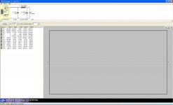
So I'm trying to get my arms around the PSUD2 thing for figuring out the power supply for my RH84. I'm pretty sure I'm doing it wrong, or maybe just reading it wrong, but it doesn't look right.
I'm planning on using the 5v4g rectifier, probably the Russian EL84 tubes, and the 6AU6 drivers.
Attached is the simulation and I'd really appreciate any help/explanation you can offer.
Attachments
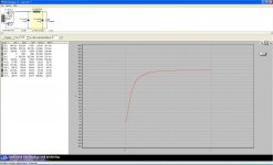
Thanks for the quick response; that's just what I needed. Now I just need to know what numbers I want to look for; max voltage? RMS? Mean?
Look at the voltage which the curve reaches, thats your boy.
Is there overshoot or ringing (both bad). If it slowly and steadily rises to a stable voltage then you are good.
You can zoom in on the curve by selecting an area of it, good for looking for ringing and finding residual ripple.
Shoog
Is there overshoot or ringing (both bad). If it slowly and steadily rises to a stable voltage then you are good.
You can zoom in on the curve by selecting an area of it, good for looking for ringing and finding residual ripple.
Shoog
All right, I think I'm getting closer. Next question, I believe I was supposed to be hitting around 300V but for the RH84 but it looks like I'm closer to 330V.
I tried switching the rectifier to a 5u4g, upped the choke, played with the caps, and it still stays way above 300.
I tried switching the rectifier to a 5u4g, upped the choke, played with the caps, and it still stays way above 300.
Attachments
Consider the situation where there is a 100% Schade feedback and the feedback resistor is also the load resistor of the driver.
Where is the voltage gain coming from - from the driver current over the feedback resistor.
Where is the current gain coming from - from the output valve fighting its own grid change.
Reading the Tubecad article leaves you with a quite different feel for what is going on in this circuit. Its certainly a good supplement to other understandings.
Shoog
- Status
- Not open for further replies.
- Home
- Amplifiers
- Tubes / Valves
- RH84 SE, pentode driver... advice please