Will throw up some pictures but you will have to wait till Tue since I am away for a few days. Its not an elegant build since I squashed it into an old guitar amp case, but hopefully it will show how little there is to it.Any dead bug or "mounted on scrap wood with bailing wire and alligator clips" pictures? Just wanting to see what this looks like in real life because a ne killer design sure has me curious.
Shoog
Shure, even with a missing leak resistance on the control gridit biases up fine, but extra headroom cannot hurt.
However your suggestion will not work as shown since there is no longer any room in the positive direction of the slaved tetrode for current matching.
Shoog

Your remark give the impression you don't now how that system works
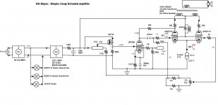
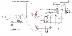
A drawing with some changes and expected voltages,
Mona
Attachments
it has high distortion because the outputs are not driven balanced.
It's a differential power amplifier. The right side is cathode-driven and has essentially perfect AC balance if the CCS is perfect.
The self splitter power LTP fell out of favour way back in the early days of valve design because it had fairly terrible performance. this was because it used either a low value resistor for the tail which unbalanced the LTP badly or a poor pentode CCS.it has high distortion because the outputs are not driven balanced.
he is driving one tube with signal while the other is only seeing bias. (schade)
he could add an inverted splitter and gain pot to drive the second tube from 0 to 100% to gauge the difference.
Now days its a trivial matter to build a CCS with almost infinite impedance which will ensure that the slaved valve gets an almost perfect copy of the input signal of the driven valve. This means that a power LTP should perform at almost the same level as a cathodyne or a LTP phases splitter front end.
Also there is more going on with this design than a simple self splitter output stage which means that its behaviour is far more akin to a Single Ended output stage.
Shoog
Shure, even with a missing leak resistance on the control grid
Your remark give the impression you don't now how that system works
A drawing with some changes and expected voltages,
Mona
Ok I see now, and its an improvement to eliminate the whole bias transformer from the design making it easier and cheaper to build.
Shoog
I have had great success using the 6AU6 with none of the microphonic issues some people have claimed. Its relatively cheap and plentiful and is right smack bang in the correct voltage range for this design.Why not consider a 6Ж9П (6J9P), allmost the EF184 and cheap.
Mona
It was my hope to use the EF91 simply because it is a dowdy unloved little valve that is probably the most plentiful but cheapest pentode in the world, however the screen rating are given for values of 200+V which would have placed the screen way above the plate which is not ideal. It might have been possible to get it to operate at a 150V screen but the likely hit would have been an uncomfortably small g1 voltage which would have invited grid current problems.
It would also have been nice to use an all B9A complement which would have made base sourcing easier, but most of the small signal pentodes have tiny current capabilities (hence the attractiveness of the EF91 with its 10mA rating).
Isn't the 6J9P a remote cuttoff valve ?
Shoog
Last edited:
No, but the EF91 is.Isn't the 6J9P a remote cuttoff valve ?
Shoog
Mona
Ok there's an interesting result to report.
The 6AU6 and the E180F are drop in replacements for each other voltage wise, but the voltage out of the E180F is 3x that of the 6AU6 and the distortion profile of the E180F has about equal 2nd and 3rd harmonic at -65db down (slightly more third harmonic). The 6AU6 has less voltage gain but has -60db 2nd harmonic and -85db 3rd harmonic.
The 6AU6 is a clear winner harmonic distortion wise.
I will run the simulation again with the E180F and the cathode bypass cap removed to see if it improves.
UPDATE: Without the bypass the E180F has about the same ultimate voltage gain as the 6AU6 but the second harmonic is down to -80db and the third is down to about -85db, so lower overall distortion - but possibly not quite as pleasant a signature as the 6AU6.
Hard choice since 2nd harmonic masking is probably better than the ultimately lower overall distortion. i think I would call it for the 6AU6 since this design is seeking to emulate the signature of an SE amplifier.
PS - the alternative bias design simulates perfectly so I will incorporate it into a final schematic.
Shoog
Last edited:
I lashed up a spice model of the RH84 for comparison.
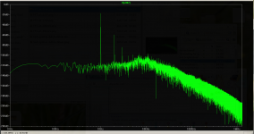
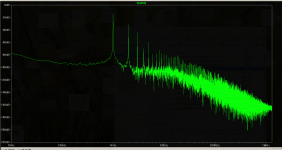
It takes 3x the input signal to get the same3 output with the RH84.
I plotted the FFT at 250mV output for each model for comparison, the RH84 looks fairly horrendous in comparison. My design first, RH second.
Shoog
It takes 3x the input signal to get the same3 output with the RH84.
I plotted the FFT at 250mV output for each model for comparison, the RH84 looks fairly horrendous in comparison. My design first, RH second.
Shoog
Attachments
Why 250mV, isn't that really low output? Since the RH design relies heavily on inter-stage distortion cancellation, may be its THD profile improves at higher output level?the RH84 looks fairly horrendous in comparison.
Thats the first simulation I ran for comparison. I will run some at different levels to get the full picture, but if it distorts badly at low levels that got to be a very bad sign of the inherent problems I have been banging on about.Why 250mV, isn't that really low output? Since the RH design relies heavily on inter-stage distortion cancellation, may be its THD profile improves at higher output level?
No one should want a design which distorts more at lower signal levels since that is where the majority of the listening will take place.
Shoog
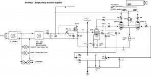
The (final) 6AU6 version of the schematic.
Shoog
MonaAttachments
- Status
- This old topic is closed. If you want to reopen this topic, contact a moderator using the "Report Post" button.
- Home
- Amplifiers
- Tubes / Valves
- RH slayer