Hi all,
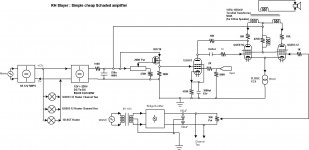
I recently built a very simple little amplifier which I though would be worth sharing. People might know that I have been a violent critique of the whole RH amp concept because of its inherent design flaws. I decided to see if I could design a simple cheap Schaded amplifier based upon a sound understanding of the principles of Schaded feedback. This is what I came up with.
Things to note are:
-it uses a Switch mode Power supply to generate a 12V regulated supply for the heaters and to feed the +B power supply. One of these can be had for €10.00 from:
AC 85 265V TO DC 12V 8A AC DC 50 60Hz Switching Power Supply SMPS Moudle Board | eBay
-the B+ is generated by using a boost supply which generates 230V DC. This can be had for €10.00 from:
150W Inverter Battery DC 12V TO DC 220V Voltage Step UP Boost Converter Module | eBay
At the power levels this unit is operated at there is no need for the fan which has an slight hum to it.
-the valves themselves are Russian dual tetrodes which I got from an eastern european suppler €12.00 (inc. P+P) for a quad.
-the toroidals used for the output need only be small 40-50VA units and can be had for about €15.00 a throw.
-the only really expensive item is the 12L8GT which is an obscure twin pentode valve which I used because I wanted a three valve design. Its quite expensive and generally only available from America. I will be working up a design which uses either the 6AU6 or the even cheaper EF91 which can be had for peanuts.
It should be possible to build this unit for less than a €100.00
The bias adjustment is used to ensure that the voltages at the top of the tetrode plates are exactly equal, which ensures that the DC standing current in the transformer are equal on both sides.
The pot on the IRF710 is used to set the voltage drop across the driver 10K plate load to about 80V.
I built the bias adjuster on a little perf board and used a salvaged 8+8V transformer. Any small dual secondary transformer of low voltage will do.
I also used tag strips to mount most of the components on.
The unit will produce about 5W of power per channel. This has an overwhelmingly second harmonic distortion profile and it measures very like a Triode SE design. It is not an ultra low distortion design and was not designed to be such. I am listening to it on my secondary system and it matches up extremely well to any of my other designs.
Shoog
Attachments
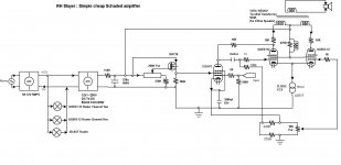
Missed a smoothing cap on the bias supply
The 670R resistor on the screens of the dual tetrode has enamelled wire wrapped round it 10 times and is soldered to each lead of the resistor. This offers no resistance at frequencies below RF, but kills any tendency to RF instability. The 10R resistor on the plates should be soldered right on the pins of the valve base for the same reason.
The 670R resistor on the screens of the dual tetrode has enamelled wire wrapped round it 10 times and is soldered to each lead of the resistor. This offers no resistance at frequencies below RF, but kills any tendency to RF instability. The 10R resistor on the plates should be soldered right on the pins of the valve base for the same reason.
Attachments

Last edited:
Maybe you meant to say 'critic'? Unless, of course, you are not a person but an argument personified!Shoog said:I have been a violent critique
The reason you get overwhelmingly second harmonic distortion is because the driven tetrode is Schaded to the driver which turns its character into a pseudo triode. the second tetrode is running as a pure tetrode which means it is slaved to follow the signal fed it by the driven tetrode - which it does very well. Secondly the current through the transformer is unbalanced by the bleeding off of the driver plate current - which in turn contributes to a second harmonic character.
Shoog
Shoog
I believe only if the behaviour of the two elements are identical.
Take for example a not very well matched pair of triodes in PP, it will have a higher second harmonic distortion than one which has a matched pair.
The simulation results confirm this behaviour. In this design the two elements are extremely poorly matched.
Shoog
Take for example a not very well matched pair of triodes in PP, it will have a higher second harmonic distortion than one which has a matched pair.
The simulation results confirm this behaviour. In this design the two elements are extremely poorly matched.
Shoog
I asked the same thing on my own thread http://www.diyaudio.com/forums/tube...n-self-inverting-push-pull-anti-triode-2.html
Is that a veiled insult?Looks somewhat like the oddwatt.

I'd love to see distortion spectra if you have them to post. It would be interesting to put them side-by-side with an RH and see what the difference in spectra are at different comparable power levels.
Overall, it looks very cheap and like a very good concept.
Have you tried it without bypassing the input pentode's cathode? I know it would reduce gain but it would be interesting to see the effect on the linearization you would get in the input pentode's V-to-I characteristics and how that would impact the system overall. Of course, that would also impact the rp of the input tube as well and affect your "Schade" feedback ratio.
it biases up fine, but extra headroom cannot hurt.Looks somewhat like the oddwatt.
The control grids must be positive biased to give room for the current source.We allready have round 9V on the cathode of the drivertube, let's use that.
Mona
However your suggestion will not work as shown since there is no longer any room in the positive direction of the slaved tetrode for current matching.
Shoog
Last edited:
I only have simulations, which i would have to drag out.I'd love to see distortion spectra if you have them to post. It would be interesting to put them side-by-side with an RH and see what the difference in spectra are at different comparable power levels.
Overall, it looks very cheap and like a very good concept.
Have you tried it without bypassing the input pentode's cathode? I know it would reduce gain but it would be interesting to see the effect on the linearization you would get in the input pentode's V-to-I characteristics and how that would impact the system overall. Of course, that would also impact the rp of the input tube as well and affect your "Schade" feedback ratio.
It is necessary to bypass the cathode of the 12L8GT since it is a shared cathode tube, which is the only way to isolate the two pentodes. Also the gain of the 12L8GT in this circuit is very low so without the bypass it would need another gainstage.
However when I work up my version with the EF91 I will try it with and without the bypass.
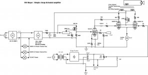
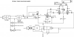
Small correction to the circuit, the driver cathode resistor for the 12L8GT is in fact 235R (two parallleded 470R). This mistake is a carry over from the simulation in which I had to substitute a similar pentode due to lack of model.
Surprisingly enough the feedback ratio seems to have very little impact on the overall performance of the amp. i tried various different ways of feeding part of the drivers current from the B+ to increase the feedback resistor (reduce the feedback) - and it made almost no impact on the distortion (slightly worsened). The direct 10K resistor was the most straightforward and economical methods in the end.
Shoog
Attachments
Last edited:
Would love to hear your impressions, will you wait for a less obscure driver pentode ??Cool, guys, I will have to breadboard one and check it out for myself, although I must say that I am not a fan of the self-split output stage...
Shoog
Your shooting for 8-9mA plate current with 200V on the screen. I think I modeled it originally with a 6AU6 which gave the 470R cathode resistor.Yes, I will try to use whatever I have on hand.
Shoog
- Status
- This old topic is closed. If you want to reopen this topic, contact a moderator using the "Report Post" button.
- Home
- Amplifiers
- Tubes / Valves
- RH slayer