You can thank the gutless manufacturers for that.
Did you look up the iraudamp files. The reference designs are often just dropped into an amp. It saves the manufacturers the cost of R&D and testing.
Did you look up the iraudamp files. The reference designs are often just dropped into an amp. It saves the manufacturers the cost of R&D and testing.
The Vaa and Vss can run off resistors to the rails.
Or they can be run off regulators or zeners.
However there are limits on the voltage as 2092 has internal zeners too.
Or they can be run off regulators or zeners.
However there are limits on the voltage as 2092 has internal zeners too.
This amp uses +/-5v regulators, they appear to be working fine. But for some reason Vaa is being dragged down at pin 1 of the chip, I’m gonna be really annoyed if they were both bad from the supply house. I’m using the AUIRS2092STR from Mouser to replace the factory unit which was an IRS2092S.
Perry: looked at those design sheets, this appears to be closest to the #9 one with the totem pole drivers. Other than that the only other differences I can see are the regulated Vaa/Vss this board has. The #9 sheet simply uses resistors off the rail for that purpose.
Perry: looked at those design sheets, this appears to be closest to the #9 one with the totem pole drivers. Other than that the only other differences I can see are the regulated Vaa/Vss this board has. The #9 sheet simply uses resistors off the rail for that purpose.
Last edited:
On my amp its a zener and a 10uf cap on the Vaa rail.
If yours has a cap maybe its shorted ?
Other that that then maybe another bad 2092 ?
If yours has a cap maybe its shorted ?
Other that that then maybe another bad 2092 ?
Removed the IC yet again, pin 1 voltage on the board returned to 5v. It appears I got 2 bad chips from Mouser, imagine that. I’ll send them mail on Monday, hopefully they will send me replacements.
Thankfully they volunteered to send me a pair of new chips, they got here today but I won't have a chance to play with it till probably the weekend.
Officially stumped.
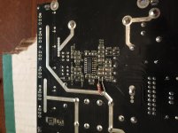
Soldered in a new chip, same result. VSS reads -5v as it should, but VAA is still dropping down to around .8v for seemingly no reason. Attaching a pic for reference, the leaded resistor is in series between the positive regulator and the VAA pin. The regulator side of it is at 5v, chip side is .8v.
Only thing I can think is maybe the AUIRS2092STR I’m using doesn’t like this circuit, which originally had a standard IRS2092S in it. But I can’t think of a reason why it would matter, the spec sheets look identical to me.
Attachments
Referred back to the IRAUD5 supplement which had a 10R resistor in that spot, and decided to give that a shot instead of the one that was in there. It worked! I now have output oscillation and there’s no DC at the speaker terminals, so I think I’m good to do final assembly. No idea why the resistor I removed from that spot read so high, maybe the old chip shorted and burned it out.
Officially stumped.
Soldered in a new chip, same result. VSS reads -5v as it should, but VAA is still dropping down to around .8v for seemingly no reason. Attaching a pic for reference, the leaded resistor is in series between the positive regulator and the VAA pin. The regulator side of it is at 5v, chip side is .8v.
Only thing I can think is maybe the AUIRS2092STR I’m using doesn’t like this circuit, which originally had a standard IRS2092S in it. But I can’t think of a reason why it would matter, the spec sheets look identical to me.
If its a resistor between regulator and Vaa its very high value at 2k2.
No wonder it didnt work.
Not even sure why it needs a resistor.
Not sure why it needs to be there either. It’s possible it had drifted high when the original chip failed and I just wasn’t paying attention to the value when I replaced it, I sometimes overlook stuff like that. I helped in this case to have the additional references though, I measured the resistance between VSS and the neg regulator and there’s 10R there as well. Must be the way it’s supposed to be I guess.
Got all the new silicon soldered in, but I have to repair the output terminals before I do final testing on it. They are apparently made of pot metal and snapped off near the board, I think I can use tiny screws to attach short copper bussbars to it.
Test thoroughly. The 'typical application diagram' in the datasheet shows it working with a 2.7k resistor.
Is the filter cap for the VAA heating up?
Is the filter cap for the VAA heating up?
That’s for when VAA receives power from the positive rail, which is quite a bit higher than the 5v the chip is seeing here. I suppose it’s possible the wrong part got put there by mistake as well since the amp looks physically new, I’ve seen stranger things. Haven’t checked the cap, I’ll make it a point to check.
Last edited:
I would be having a look at the schematic to see what that resistor does.
As said by miniman82 the Vaa can be run off b+ via a dropper or a regulator/zener setup.
Could be the pcb is multi-purpose.
As said by miniman82 the Vaa can be run off b+ via a dropper or a regulator/zener setup.
Could be the pcb is multi-purpose.
- Home
- General Interest
- Car Audio
- RF Prime 1200.1D/IRS2092S