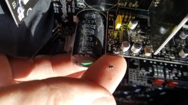
This is the best I can do for a size comparison.
Attachments
Last edited:
Probably. It's the other PNP driver. It's connected to Q105.
Btw, I was talking about the one above and over, I believe it is marked 103 but you can't really see the number that good. It is the same part number as the one that is removed.
The specs are the same but the case is sot-323 instead of sot-23. The correct one for that manufacturer would have had a PMBT prefix.
The original drivers are the MMBT3904 and MMBT3906. Order both.
Correct, Q103 is the other 2A driver.
Did you check the gate resistors?
The original drivers are the MMBT3904 and MMBT3906. Order both.
Correct, Q103 is the other 2A driver.
Did you check the gate resistors?
Where are the gate resistors?
Also, I already have the PMST3906's. Do I need to get the MMBT? I noticed that the only difference is a difference in mW, one is 200 and the other is 300 respectively. I forgot what that spec was for, but you said I'd be ok with the PMST's. Also, I don't think any NPN's are bad, not by the looks anyway. Are you saying I should change every single transistor on that board?
Correct, Q103 is the other 2A driver.
Did you mean point .2A driver?
Last edited:
If you can make the leads reach the pads, I think they would work but it would be better to have the right ones. If nothing else, you can use them for testing to see if there are any other problems.
I wanted to ask about ChipQuik. I've had it for some time now, but all it is is alcohol pads, a tube of flux I guess and a length of solder? I assume the flux and the solder are the key. But how does it make it so much easier? Does it make the solder take longer to harden when you add their metal and flux?
Btw, I ordered the correct npn and pnp transistors from digikey. Just waiting now. . .
Btw, I ordered the correct npn and pnp transistors from digikey. Just waiting now. . .
ChipQuik is a different alloy than regular solder. It melts at a very low temperature. You remove as much of the regular solder as possible and add the CQ. The flux helps it flow and is required because it doesn't have a flux core like normal solder.
The low temp allows you to get all pins hot enough to remove all pins at once without having to remove all of the solder. It's easier to get all pins to the low melting point of the CQ alloy. To do this with regular solder, you would risk delaminating the main board. Then you desolder the holes.
I'd recommend, after desoldering the pins and the vias that you go back and add regular solder and desolder again to remove most all of the low temp alloy.
Toss the alcohol pads or use them for something else. Use acetone, paper towels and a toothbrush to clean the flux.
Thank you for the info. I may try to take the board out if I need to do more than one transistor.
Upon further inspection, I have found along every single one of the output transistors, there is at least one resistor with dead shorts. All of the blue ones with gold ends, I cannot get in there to see the value, and some reading 37R4 and 10R0. Do you know if this is normal? None appear burnt.
Upon further inspection, I have found along every single one of the output transistors, there is at least one resistor with dead shorts. All of the blue ones with gold ends, I cannot get in there to see the value, and some reading 37R4 and 10R0. Do you know if this is normal? None appear burnt.
It appears that you may be reading across the protection circuit resistors which are in parallel with the 0.1 ohm source resistor. This will make them read low.
If it turns out that that's wrong, post a photo of the resistors. I have absolutely nothing on this amp.
Oh, really? I just assumed you did b/c of the picture of the driver board you sent me, it didn't occur to me that it could have been somebody else's! Ok. . . I received more power supply transistors today and next week the output transistors are coming along with the driver transistors. I also ordered a bunch of parts for a diy amp that I'm going to build for learning purposes. Here it is if you or anyone else is interested, although it is a class D.
https://www.allaboutcircuits.com/projects/how-to-build-a-class-d-power-amplifier/
https://www.allaboutcircuits.com/projects/how-to-build-a-class-d-power-amplifier/
My photo, from a P400-4.
Start a new thread if you have questions, in the class D forum may be best. One note, the amp has no input circuit to eliminate ground loops. You'll have to use an isolated power supply (isolated secondary) or ground loop isolator on the input.
If you go to another forum, they may try to switch you to a self oscillating design. The clocked design (triangle waveform fed into comparator) allows easier step by step troubleshooting, in my opinion.
Again, start a new thread if your questions don't apply to the original repair.
Nah, that's just a side project, my main goal is to get this amp fixed, but with the diy amp, I'm just tinkering, killing time until all of my parts are here for the RF. Should I attempt taking the daughter board off, or just try replacing that one transistor and then power up with the remote 12V and probe? I'd be afraid of causing more problems if I try to take the board off. But I'd like to hear your suggestions.
Thanks
Thanks
As with most Rockford amps, you can connect only remote and ground and check the drive signal with little risk to anything.
You'll replace the other 2A transistor that's damaged as well.
You'll replace the other 2A transistor that's damaged as well.
Ok, thanks Perry. Will be back as soon as the parts come. B/c I really have no idea what I'm checking with just the remote powered. Voltage, etc.
Thanks
Thanks
- Status
- Not open for further replies.
- Home
- General Interest
- Car Audio
- RF Power T600 Short Plz HELP!!!