I had enclosed the data sheet in my previous post. I used this part in several designs during my career at Motorola which ended in 2014. The part is NRND now, though DigiKey still has a few in stock.
It reveals a power output of 11 watts @ 100Mhz with an efficiency of 55%, so 20 watts of DC into the device gets you about 11 watts of RF out at 100 MHz. This degrades to 6.5 watts output @ 900 MHz with a 34% efficiency, so 19 watts of DC into the device gets you 6.5 watts of RF out at 900 Mhz.
The part is internally matched to 50 ohms across the 50 MHz to 950 MHz range. It also has a nearly constant 23 dB gain from 100 MHz to 930 MHz. This means that a harmonic filter is required on its output if this will be used in a transmitter application. I used a switched filter bank to cover 136 to 936 MHz. My filter had over 1 dB of loss at 900 MHz considerably reducing the available power to the antenna.
There are probably better choices for a broadband transmitter today, but I really haven't paid much attention to the RF device world since I left Motorola.
Transmission line transformers typically need coax transmission lines on the order of a wavelength. Which won't be practical at audio. The diagram shown above just becomes a series chain of auto step-down transformers at audio.
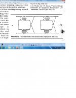
Many moons ago I suggested a patent work-around to the Berning impedance converter. Which could be adapted to DDS nicely. You start with a two phase (ie, full wave) voltage multiplier stack (diagram below from Wikipedia),

A tube then connects across the +V to 0 V. Two such assemblies then provide for P-P operation. Output at low impedance is done using the high current end (HF xfmr primary, driven by Mosfets in series with the speaker from + and - rails, just as in the Berning design). This would be using HF switching of the Mosfets, like in the Berning design. Normally the tubes would just be doing audio band linear operation. But for DDS synthesis, they would be in On/Off switchmode synchronism with the HF (with many stages in the multiplier units and higher freq. operation for DDS). The multiplier string effectively sums capacitor currents over the whole string, so effectively acts as the LP filter for audio baseband for the DDS operation. The xfmr is a small HF ferrite unit with modest # of turns on the HV side (unlike the Berning design), so easy to make and little distributed capacitance or leakage L.
So net result is NO big audio type xfmr,, baseband filtering is inherent in the design, tubes operate efficiently in On/Off mode, No hassles with the Berning patent, although I think that has expired anyway.
Even for audio baseband operation of the tubes, the shunt capacitance from the multiplier can be less than a typical audio OT, due to the HF operation shrinking the capacitors to pF size. The ferrite xfmr(s) can be made resonant with the stack capacitance for easy zero current operation (Zero crossover current Mosfet switching).
Many moons ago I suggested a patent work-around to the Berning impedance converter. Which could be adapted to DDS nicely. You start with a two phase (ie, full wave) voltage multiplier stack (diagram below from Wikipedia),
A tube then connects across the +V to 0 V. Two such assemblies then provide for P-P operation. Output at low impedance is done using the high current end (HF xfmr primary, driven by Mosfets in series with the speaker from + and - rails, just as in the Berning design). This would be using HF switching of the Mosfets, like in the Berning design. Normally the tubes would just be doing audio band linear operation. But for DDS synthesis, they would be in On/Off switchmode synchronism with the HF (with many stages in the multiplier units and higher freq. operation for DDS). The multiplier string effectively sums capacitor currents over the whole string, so effectively acts as the LP filter for audio baseband for the DDS operation. The xfmr is a small HF ferrite unit with modest # of turns on the HV side (unlike the Berning design), so easy to make and little distributed capacitance or leakage L.
So net result is NO big audio type xfmr,, baseband filtering is inherent in the design, tubes operate efficiently in On/Off mode, No hassles with the Berning patent, although I think that has expired anyway.
Even for audio baseband operation of the tubes, the shunt capacitance from the multiplier can be less than a typical audio OT, due to the HF operation shrinking the capacitors to pF size. The ferrite xfmr(s) can be made resonant with the stack capacitance for easy zero current operation (Zero crossover current Mosfet switching).
Last edited:
Looks like DDS requires an inordinate amount of filtering and VHF to get low distortion. Maybe use PWM for the tubes with a small inductor in series with the plates to get a "linear" response. The multi-stage V-multiplier then just removes the HF ripple. The # of multiplier stages then equals the Sqrt of the impedance ratio needed.
If DDS is a requirement, the DDS could run in VHF with the plate inductors in place, and the V multiplier runs at HF.
If DDS is a requirement, the DDS could run in VHF with the plate inductors in place, and the V multiplier runs at HF.
Last edited: