Here was my first attempt, but I didn't really like how it was coming out. I was thinking after doing a left and right version with an RCA connector on board each that would protrude through the back cover to remove signal/noise antenna wires.
Interesting concept 😉
And a good idea to use 4-pin connectors

Almost ready!
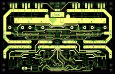
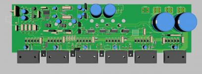
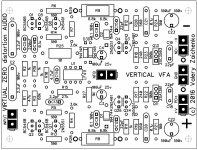
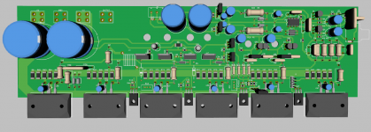
Here is what I came to now. Separate connectors to the IPS and OPS rails and grounds, coming together at PSU module. 3 x TO-264 or 2 x MT-200 output devices would fit at the back.
Careful ground layout for the lowest artifacts.
I will clean-up the silk screen and... probably order some boards for testing 😎
220 mm x 140 mm
Attachments
Last edited:
hi vzaichenko
I really like this design.
I want to try to set up the output stage so , do you have any suggestions?
Hi Veysel,
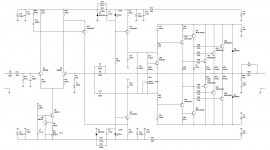
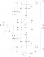
I have worked on simulations - here is what I see.
In general - a very cool amp. The only thing, which is a bit tricky - Sziklai drivers. You can see the phase hump at around 3MHz - that's Sziklai.
I had to use the models for MJE15032/33 as I've got no models for 2SC3298/A1306, so in reality the picture may be slightly different. This is just a "heads up" on potential area to be careful with. Also - C21, C23 help a lot.
If you can test the live prototype and see if there are no stability issues - that would be cool! 😎
Attached is the schematic I analyzed.
Cheers,
Valery
Attachments
I've got one channel to where I'm almost happy with the outcome. Now I'm debating using 6800uF caps on the main rail feeds and installing fuses after them. Would there be any advantage to having large local reservoir caps?
Looks good, although there seem to be some tricky points, like small caps between MT-200's leads 🙂
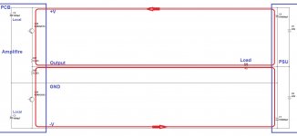
I don't think large local reservoir caps give some real advantage. The main caps array, connected with the good thick wires, does the job. See the picture attached. In case the load ground return is connected the right way (directly to PSU), the high currents, going through the load, circulate via the reg-marked paths. The local Amp PCB ground is the longer way to go - it's more a reference for the front-end, not the "power" ground. Local caps eliminate some possible ripple - that's fine - but they don't really need to be of high values.
Attachments
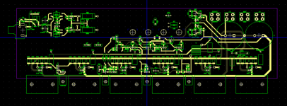
I'm laying it out to lay flat on a 6" x 12" heat sink on 1/2" standoffs. The output transistors will connect from below, so there's lots of room for those caps. With the board mounted near the top of the heat sink, the output transistors will be approximately 2" from the bottom, which should be around the optimum height for cooling.
Good point about the speaker return ground. I'm not used to having empty space on a PC board. Just trying to think of a way to put it to use.
Good point about the speaker return ground. I'm not used to having empty space on a PC board. Just trying to think of a way to put it to use.
Revox B285
jwilhelm
Revox B285 also share current in an intermediate stage between Q105 and two CCS (Q102+Q124) like your power amplifier. It is an good sounding product of 80's
Regards
Ronaldo
jwilhelm
Revox B285 also share current in an intermediate stage between Q105 and two CCS (Q102+Q124) like your power amplifier. It is an good sounding product of 80's
Regards
Ronaldo
Attachments
Last edited:
jwilhelm
Revox B285 also share current in an intermediate stage between Q105 and two CCS (Q102+Q124) like your power amplifier. It is an good sounding product of 80's
Regards
Ronaldo
Hi Ronaldo,
Interesting 🙂 I came to the very similar topology independently some 30 years later 😛
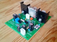
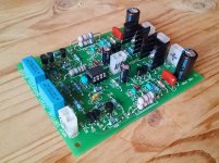
Here are the live measurements of my amp with this kind of the front-end:
Ampliwire + NS-OPS
Photo is my front-end PCB.
Cheers,
Valery
Attachments
VERTICAL VFA - excellent!
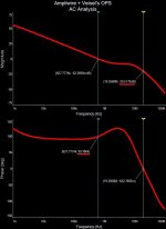
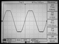
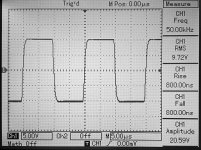
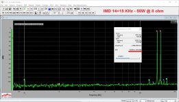
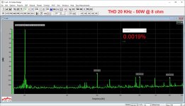
Just tested the new VERTICAL VFA front-end. As expected - this is a CFA-fast VFA. Measurements are performed in combination with NS-OPS.
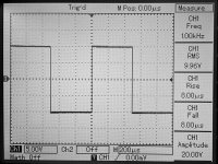
Great phase response, low THD / IMD, accurate square wave response, 800nS raise/fall time, unconditional stability - very fine IPS module. No need to set/tune anything, if soldered correctly - works right away. Clean clipping.
Next post - "as built" schematic and a photo.
Cheers,
Valery
P.S. Cool feature - it can be easily adapted to virtually any rails up to, say, +/-90V - only R8/28 and R9/29 may need to be changed. All the rest will work "as is".
In the range of +/-50V ... +/-70V it will work "as is". So, 250W @ 8 ohm swing - no problem 😉
Just tested the new VERTICAL VFA front-end. As expected - this is a CFA-fast VFA. Measurements are performed in combination with NS-OPS.
Great phase response, low THD / IMD, accurate square wave response, 800nS raise/fall time, unconditional stability - very fine IPS module. No need to set/tune anything, if soldered correctly - works right away. Clean clipping.
Next post - "as built" schematic and a photo.
Cheers,
Valery
P.S. Cool feature - it can be easily adapted to virtually any rails up to, say, +/-90V - only R8/28 and R9/29 may need to be changed. All the rest will work "as is".
In the range of +/-50V ... +/-70V it will work "as is". So, 250W @ 8 ohm swing - no problem 😉
Attachments
-
 DSC_0281.JPG448.4 KB · Views: 179
 -
 DSC_0279.JPG515.3 KB · Views: 193
 -
 DSC_0278.JPG433.9 KB · Views: 177
 -
 DSC_0277.JPG478 KB · Views: 187
 -
 11-imd-14-15khz.JPG283.7 KB · Views: 226
 -
 10-thd-020khz.JPG277.1 KB · Views: 220
 -
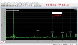 10-thd-010khz.JPG267.7 KB · Views: 224
 -
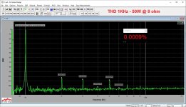 10-thd-001khz.JPG288.6 KB · Views: 252
 -
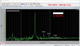 09-thd-300hz.JPG320.5 KB · Views: 317
 -
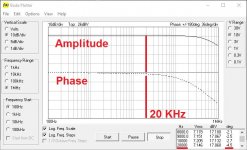 05-bode-1MHz.JPG104.1 KB · Views: 347
Last edited:
I've got the second channel layed out. I just need to double check all the clearances and touch up the silkscreen, and my 250W monsters will be starting to take shape.
Yeah... this will be a hell of an amp!

In case you will like the VFA version - very easy to adapt, minimum changes in IPS area 😉
Yeah... this will be a hell of an amp!
In case you will like the VFA version - very easy to adapt, minimum changes in IPS area 😉
I'll have to study the schematic closely when I get a chance. Do you think it would be possible to make a dual option layout?
I'll have to study the schematic closely when I get a chance. Do you think it would be possible to make a dual option layout?
Yep. If you look at them side by side - the differences are rather small. You can place two sections at the very input - they don't take too much space.
Looking good Valery... Congrat! 😉Just tested the new VERTICAL VFA front-end. As expected - this is a CFA-fast VFA. Measurements are performed in combination with NS-OPS.
Great phase response, low THD / IMD, accurate square wave response, 800nS raise/fall time, unconditional stability - very fine IPS module. No need to set/tune anything, if soldered correctly - works right away. Clean clipping.
Could you test it later with 1-2uF load with directly @ output (with short wires)
without any output L, just if you feel it safe, of course! 🙂 Thanks!
Looking good Valery... Congrat! 😉
Could you test it later with 1-2uF load with directly @ output (with short wires)
without any output L, just if you feel it safe, of course! 🙂 Thanks!
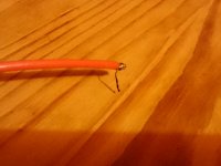
OK, I tried, but before I could take a picture of the scope screen with 20V amplitude square wave, the capacitor's lead melted and burned 😀 The picture shows a piece of the lead left on a wire. It was 1uF.
It does not oscillate or something, shows some ringing of course. But with no coil it's dangerous - currents involved are pretty high 😱 That's why we use the coil.
Attachments
Yeah... this will be a hell of an amp!
In case you will like the VFA version - very easy to adapt, minimum changes in IPS area 😉
Congrats on another great design Valery! Jeff I will be watching your progress. I cannot resist the urge. It looks like I will be building yet another amplifier.
- Home
- Amplifiers
- Solid State
- Revisiting some "old" ideas from 1970's - IPS, OPS