Thanks for that Ian, hadn't seen that one before. I think December 76 was the first issue I ever owned, and I was still at school back then 😱
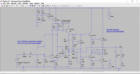
Interesting, very interesting even. A thought struck me on the weird darlington arrangement... wouldn't it be needed for his very high feedback resistor (220k). If the feedback values were lower then you would be pumping that extra current into the LTP tail, which given its just a high value resistor might not have been so good. You just wonder whether this guy had an eye (or an ear) to sonics and knew what was going to give the result he was after.
Still no emitter resistors, and still a very high zobel resistor. The 18 ohm input resistor is much higher in this earlier design and so to I think is the input coupling cap (haven't got the Europa circuit in front of me just now).
Edit... the Europa had a 1uf cap on the preamp output.
March and April 1978 for the Europa. It was an integrated amp. The April front cover brings back happy memories, I built what was on the cover, and in that specially produced case. Many many happy hours and learning followed.
http://americanradiohistory.com/Archive-Practical/Wireless/70s/PW-1978-03.pdf
http://americanradiohistory.com/Archive-Practical/Wireless/70s/PW-1978-04.pdf
No idea either on F.K. Electronics.
The twists in the design may have since been forgotten in the continuing pursuit of lowest noise and distortion. I don't know how engineer/designers viewed using other people's work in publications of the 1970s but I imagine there was a lot of industry scrutiny and bickering over who "owned" design elements and should be consulted before adopting them. I wouldn't rule out borrowing from the many IC op-amp developments in the 1970s either.
This tradition of one-upmanship and attribution in linear audio design is still alive - probably why odd ways of achieving similar ends continue to appear and keep us wondering if there is some particular benefit to be had in the resulting odd designs 😕
I think the use of high impedance around the LTP generally, has to do with the size of the feedback cap. C18, only 1uF. With the collector resistor imbalance of 820:10k and tail resistor of 27k, it seems to me a high price had to be paid all round with a dependence on very high gain. Also, I can't believe that the finished amplifier then had an extremely low noise figure of -115dB.
That noise figure does seem very optimistic. I wonder how they measured it.
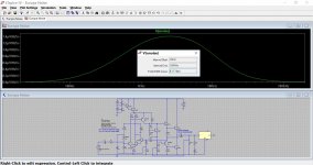
So that got me trying something on the simulation, and I hope I've done this correctly... I calculate the snr as being around -102db (that's still pretty good actually) based on the amp achieving around 18vrms output. I used Bob Cordells 'A' weighting filter to measure Vout over the 20Hz-200Khz band. Without the filter and over the 20Hz to 20Khz and its only a couple of db worse.
I'd bet real world with PSU noise and so on and its going to be nearer -90db or so. Is that really so bad though ?
Attachments
Yes, absolutely 🙂 I'm all for amplifiers that turn in great subjective results... which is what its all about at the end of the day.
This is not a good design, they should had better used the upper two transistors to implement a CCS instead of "designing" a useless sort of soft start circuitry.
Using a resistance as CCS for the LTP require more than half the supply voltage to get the circuit being functional while an active CCS get this threshold at a few volts.
Using a resistance as CCS for the LTP require more than half the supply voltage to get the circuit being functional while an active CCS get this threshold at a few volts.
So was it an inspired design ? or just another also ran from an era
that gave us the like of the Texan and numerous other offerings.
Hi,
The Texan has been reinvented / reused by Rega
in recent years in their Brio range of amplifiers.
Not an also ran, its an interesting topology.
rgds, sreten.
Last edited:
- Status
- Not open for further replies.
- Home
- Amplifiers
- Solid State
- Revisiting an old 1970's design. Was it inspired, or just an 'also ran'.