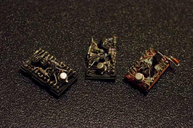
Thank you for posting that photo. It shows how the original Goldmund amplifier used a removable potted "module" which fit into the 24 pin DIP socket at center top.
The "Goldmund Clone" PCB photo in post #30, seems to have unpacked the internals of the module and laid them out as discrete components on the board. Text says "Schematic: Nagysaudio" so I visited their website and found this photo which Nagys claims to show the internal details of Goldmund modules after decapsulation. Nagys claims to have reverse engineered the modules and are offering their versions for sale, to anyone who is repairing or refurbishing a Goldmund amplifier.
_
Yes, there is a thread about it: http://www.diyaudio.com/forums/solid-state/174468-very-best-amplifier-i-have-ever-heard.html
Last edited:
Do you see that emitter is shorted to base?
You are right - it's just plain wrong.
As shown in Post #28 this particular BJT is operated in forward bias. Very unusually it is the base-to-collector junction that forward biased. Ptype base, Ntype collector. It smells like an error to me, especially since the BJT-diode is connected in series with a 6 volt zener diode.
http://www.diyaudio.com/forums/soli...plifier-i-have-ever-heard-75.html#post2337684
I posted that link just two posts back.
@obiwankenobi
Sorry but your schematic not so good ...... some errors, need to be corrected .
Why you don't use original schematic?An externally hosted image should be here but it was not working when we last tested it.
a 230:40Vac 4% regulation transformer operated on a 240Vac harmonised supply with a short term 253Vac at the primary will be OK with 63V capacitors for the local decoupling.I corrected the errors you signaled, sorry for that. The original schematic (please see post #1) indicates 63 V for this capacitors. Would you like to specify another voltage ? why ?
Vout = Vmains/230*40*(1+reg)*sqrt(2)=64.7Vpk
Subtract the rectifier diode drops and you end up with <63.3Vdc in the short term.
The smoothing capacitors in the PSU will see a short term overload (<63.7Vdc) if the amplifier is disconnected when the mains is @ 253Vac.
Using a single bridge rectifier with a higher regulation centre tapped transformer will result in a significantly higher overvoltage. Then you would have to use 75V or 80V capacitors in the PSU. The local decoupling should still be just under 63V when the amplifier is drawing it's bias current.
Last edited:
Hi friends,
First of all. Thank you very much for creating this thread!
I bought the Nagys Audio PCBs and almost every part last/this year.
PCBs are with 2 pairs of outputs, silk screen, solder mask and they are green.
I was terrified to see how difficult things got with the last thread/NagysAudio.
Hope he is well, even if his arrogance at this forum was a bit too much.
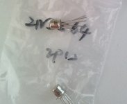
I bought a pair of 2N5564 from Ebay/China to see what I get.
I got something with very brittle legs and Idss of something like 7mA at 0VGS and 10VDS (hope I typed those the right way)
Here is a photo.
Are they fake maybe?
I really want to get this thing working together with you guys (else I sell it 😀 )
I even made the brackets already.
First of all. Thank you very much for creating this thread!
I bought the Nagys Audio PCBs and almost every part last/this year.
PCBs are with 2 pairs of outputs, silk screen, solder mask and they are green.
I was terrified to see how difficult things got with the last thread/NagysAudio.
Hope he is well, even if his arrogance at this forum was a bit too much.
I bought a pair of 2N5564 from Ebay/China to see what I get.
I got something with very brittle legs and Idss of something like 7mA at 0VGS and 10VDS (hope I typed those the right way)
Here is a photo.
Are they fake maybe?
I really want to get this thing working together with you guys (else I sell it 😀 )
I even made the brackets already.
Attachments
Idss test voltage is 15Vds, not 10Vds
the range is stated as 5mA to 30mA
use Borbely to measure Vpinchoff and then calculate gm (gfs) see if it exceeds 20mS
the range is stated as 5mA to 30mA
use Borbely to measure Vpinchoff and then calculate gm (gfs) see if it exceeds 20mS
Hello jlithen , thank you for posting. I created this thread because of 2 reasons:
First, I bought a couple of the original PC boards from Nagys Audio too, a couple of years ago, bought almost the rest of the bill of materials trusting that I would have some support from him and/or the group.
Second, I asked for help, contributed some schematics and try to re-order my mind an cooperate with other people than could be lost as me, and nobody really could help me. No answers, everybody very busy explaining how nice their amps sound, after deep re-engineering, new boards and schematics and lots of selfishness and pride.
So I came her with my box full of materials to see if out of the mess of the original project I could find some help again. Unfortunately no luck.
My intention is to get help from those who kindly can understand that there is no reason to say that this original amplifiers don't work. The personal facts about Nagys should not count here. A personal discussion conducted to leave people like me and you with a bunch of resistors and PCB out of the circuit.
To finish this old story and see if we can make this work, I am not an audio expert myself, though I assembled some simple audio amps and preamps in my life since I was 17 and I was happy with the results. I am 62 now and I still do my job well as a freelance microprocessor / microcontroller systems hardware and software designer for industrial control. In the forums I participated, I have never seen such a sad attitude from many (NOT ALL) participants, trying to show superiority in front of other interested guys. I am a teacher too, 40 years now. I spended thousands of hours helping in forums of my specialty, not making feel others like stupids, mistreating them with so much indifference. With my experience and in my subject I could easily make other feel dumbs. Instead, I tried to help, and if somebody didn't have enough level to approach the topic, I spended time kindly explaining that particular, and giving valid and useful alternatives to learn.
Nothing personal and with respect, but I didn't heard much from moderators trying to establish the order of the topic when the thread was ruined and honour such an important place as DIYaudio. Perhaps reasons may exist, it would be interesting to know them so one can learn from that and get the right position. Maybe I am misplaced and this is only for experts and high end gurus. If it is, please let me know and I will leave silently.
My feeling is that Nagys was not lying, despite your boards are different that mine, and many other untidy facts but it would be nice to make this amp work. First of all by asking again (and again) if somebody has a version of this schematic working (good or bad, noisy or not, fast or slow, hot or cold). This could be a good starting point. I had never a reply. And if nobody has one, we could try to fix something to make it happen. Of course the second versions could be better, but I don't see why this one has to be so bad.
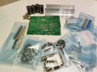
So here is my box, and I am ready to test this amp. Opinions are welcome.
With all respect
Roberto
First, I bought a couple of the original PC boards from Nagys Audio too, a couple of years ago, bought almost the rest of the bill of materials trusting that I would have some support from him and/or the group.
Second, I asked for help, contributed some schematics and try to re-order my mind an cooperate with other people than could be lost as me, and nobody really could help me. No answers, everybody very busy explaining how nice their amps sound, after deep re-engineering, new boards and schematics and lots of selfishness and pride.
So I came her with my box full of materials to see if out of the mess of the original project I could find some help again. Unfortunately no luck.
My intention is to get help from those who kindly can understand that there is no reason to say that this original amplifiers don't work. The personal facts about Nagys should not count here. A personal discussion conducted to leave people like me and you with a bunch of resistors and PCB out of the circuit.
To finish this old story and see if we can make this work, I am not an audio expert myself, though I assembled some simple audio amps and preamps in my life since I was 17 and I was happy with the results. I am 62 now and I still do my job well as a freelance microprocessor / microcontroller systems hardware and software designer for industrial control. In the forums I participated, I have never seen such a sad attitude from many (NOT ALL) participants, trying to show superiority in front of other interested guys. I am a teacher too, 40 years now. I spended thousands of hours helping in forums of my specialty, not making feel others like stupids, mistreating them with so much indifference. With my experience and in my subject I could easily make other feel dumbs. Instead, I tried to help, and if somebody didn't have enough level to approach the topic, I spended time kindly explaining that particular, and giving valid and useful alternatives to learn.
Nothing personal and with respect, but I didn't heard much from moderators trying to establish the order of the topic when the thread was ruined and honour such an important place as DIYaudio. Perhaps reasons may exist, it would be interesting to know them so one can learn from that and get the right position. Maybe I am misplaced and this is only for experts and high end gurus. If it is, please let me know and I will leave silently.
My feeling is that Nagys was not lying, despite your boards are different that mine, and many other untidy facts but it would be nice to make this amp work. First of all by asking again (and again) if somebody has a version of this schematic working (good or bad, noisy or not, fast or slow, hot or cold). This could be a good starting point. I had never a reply. And if nobody has one, we could try to fix something to make it happen. Of course the second versions could be better, but I don't see why this one has to be so bad.
So here is my box, and I am ready to test this amp. Opinions are welcome.
With all respect
Roberto
Attachments


Alright,
Nice to hear your story obiwankenobi.
Anyone heard anything from Nagys?
I'm just wondering what happened to him.
Webpage does not exist anymore.
I have once been asked to repair a Goldmund, I noticed that there were no trimmers and just a black box containing most of the parts so I gave up 🙂
At least we do not have that problem with this one.
I guess AndrewT refers to this one:
Simple circuit lets you characterize JFETs | EDN
I will try to build it and test.
Thanks for the tip!
I'm still thinking about the brittle legs...why are they that. They look a bit rough, like sanded.
Anyway. Better start soldering after the JFETs are tested...then we know if my version works.
I referred Members to Borbely.Alright,
Nice to hear your story obiwankenobi.
Anyone heard anything from Nagys?
I'm just wondering what happened to him.
Webpage does not exist anymore.
I have once been asked to repair a Goldmund, I noticed that there were no trimmers and just a black box containing most of the parts so I gave up 🙂
At least we do not have that problem with this one.
I guess AndrewT refers to this one:
Simple circuit lets you characterize JFETs | EDN
I will try to build it and test.
Thanks for the tip!
I'm still thinking about the brittle legs...why are they that. They look a bit rough, like sanded.
Anyway. Better start soldering after the JFETs are tested...then we know if my version works.
He is a reliable source for FET information.
I have done some minimal work on the amp even if I have been a bit too busy.
I did not have time to make the borbely thingie yet.
But I measured the following VGS/IDS values at VDS 15V (+ 100ohm resistor in series with Drain)
0.0V 6.45mA
0.2V 7.60mA
0.4V 8.61mA
0.5V 9.07mA
No idea if what I did was of any scientific value but datasheet states Gfs should be 7.5mS to 12.5mS.
This is something like 5mS if I did it right???
At the moment I am not super much against substituting the JFETs with something (that should work) either.
But I would like to know if I should return these to the seller and get new ones.
I do not care about my 10€, but I do care about genuinity of parts and honesty 🙂
Hi,
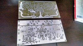
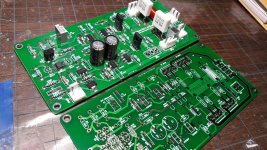
These are my own PCB. Ver.2 and Ver.3 (gold-plated)
I use SSM2212 instead of 2N5564, and it works fine.
Then, I founded some NOS 2N5564 and NPD5564, so I decided to make Ver.3, which is compatible with DIP-8, TO-71, SOIC-8. And it's gold-plated, since I think it's a mature design and already tested by Ver.2
Attachments
I have an old email from Nagys, when I bough the PCB's from him. He gave me lots of useful info at that moment that I would like to offer. Of course this is about the original schematic, not the modified versions.
About 2N5566 or similar, you can buy from here, where I've got my JFETS.
Attn:
Mr. Steve LaGaisse
RF Parts Co
ph 760-744-0700 ext.316
fax 760-744-6030
www.rfparts.com
San Marcos, CA, USA
I suggest to stick to the original parts, and I will post the Nagys email with tips.
About 2N5566 or similar, you can buy from here, where I've got my JFETS.
Attn:
Mr. Steve LaGaisse
RF Parts Co
ph 760-744-0700 ext.316
fax 760-744-6030
www.rfparts.com
San Marcos, CA, USA
I suggest to stick to the original parts, and I will post the Nagys email with tips.
Here I am transcribing some useful data from Nagys when he shipped my PCB's to me. They are all separate paragraphs, but they make perfect sense.
Hi Roberto,
I've shipped the PCB boards first thing this morning. You should get them in a few days. I've included a print out of the layout as well as the schematic. Also, please find attached in this email an electronic version of the layout plus schematic. Goldmund Mimesis 3 is the very best amplifier I have ever heard, once you're done I hope you agree. I wish you the best of luck with it. If you need any help, please don't hesitate to write me an email.
Regards,
Norbert
-------------------------------
Hi Roberto,
- Toshiba 2SK134/2SJ49 = Magnatec BUZ900/BUZ905, or BUZ901/BUZ906 (available at Newark, Farnell, eBay, etc.)
- MPSA93/MPSA43 = MPSA92/MPSA42 (available at Newark, Mouser, Farnell, DigiKey, eBay, etc.)
- BD250C/BD249C (available at Newark, Farnell, eBay, etc.)
- BC546B (available at Newark, Mouser, DigiKey,eBay, etc.)
- BC182B (available at Mouser, eBay, etc.)
-2N5565 = 2N5564/2N5566 (available at eBay and a bunch of other places from China online) also, the 2N5566, last I've checked, is available at www.rfparts.com, you can contact Steve Lagaisse at 760-744-0700 ext. 316 to order them.
- BC556B = (available at Newark, Mouser, DigiKey, eBay, etc.)
- BC449 = MPSA06/BC546B (available at newark, Mouser, DigiKey, eBay, etc.)
This is the complete transistor reference list for the Goldmund Mimesis 3 amplifier. I won't include another one, so please print this one out. The hardest part to find is the 2N5564/2N5565/2N5566 dual j-fet, as they have no equivalents. But if you do some searching online, you should be able to come up with a few more sources than the ones I've listed above.
The MOSFETS you'll have to match. I cannot help you there as I do not sell any parts, nor have any of these MOSFETS in stock myself. You might have to order a few extra ones in case they don't match up too well. If you need the correct procedure on matching MOSFETS, please do a search online, there are hundreds of references.
Everything else you should be able to easily find on Newark, Mouser, DigiKey, Farnell, eBay, etc.
For heatsinks, my favorite place to purchase from is HeatsinkUSA
My favorite toroidal transformers are the Avel Lindberg. You can talk to Melanie Roman there, she's a very pleasant person to deal with.
Please understand, this is a solid state amplifier and unlike a tube amplifier, it requires a good understanding of electronics in order to build it. After you've finished it, the amplifier should be tested for oscillations. Depending on your grounding scheme, the length of input/output wires, chassis, board orientation, etc. you might have to play with the small capacitor values (4.7pF, 8.2pF, 10pF, 47pF, etc.), or even strategically add new ones.
I will supply you the complete original schematic for the Goldmund Mimesis 3 amplifier and the parts layout for the PCB boards. Unfortunately, everything else will be up to you to figure out and my help will be very limited. If this is acceptable to you, I'll get the boards out to you tomorrow morning. If not, I can send you a refund. There are no returns/refunds once the boards have shipped.
Regards,
Norbert
-------------------------------
Roberto:
Heatsink: I like this one in 3" height. But what you use is really up to you and the size of chassis that you build for the amplifier. 10.080" - HeatsinkUSA
For smaller electrolytic capacitors, I like to use Panasonic FC series. For larger ones, I like the Panasonic PSU series, or Cornell. 95% percent of all the Panasonic capacitors use standard lead spacing and should work in the Goldmund Clone PCB. But you should always double check the datasheet before ordering. My favorite place to order these capacitors is from DigiKey Electronics - Electronic Components Distributor they even list the lead spacing of all the Panasonic capacitors and they have all the ones you'll need in stock.
Goldmund does not specify the inner diameter of this coil. Although I've looked inside the amplifier and it's about the same size as a round pencil/pen. This capacitor I would recommend that you make yourself by twisting 22 turns of magnet wire around a standard round pencil. I would either use 18AWG wire, or 16AWG. Both will work with the PCB. If you don't have magnet wire, you can buy a small value inductor from a variety of DIY speaker online shops, Madisound Portal , Parts Express: the #1 source for audio, video & speaker building components , The world leading producer of "high-end" crossover components , etc. You can unwind this inductor and make the coil.
BD249/250C: No heatsink is needed. If you do want to use one, any heatsink that will work with a TO-218 case is fine. Virtually all distributors stock these.
About R8: The amplifier's output has to show 0 volts, or close to it (0-20mV). You'll have to measure the output before the Zobel and RL circuits.
MOSFET's best match: http://www.passdiy.com/pdf/mos.pdf
About using a Variac for first power on: I would first build the board without the output MOSFETS, turn it on and see how it does. If everything looks good, them install the MOSFETS. I would not bother with a variac.
-------------------------------
Hi Roberto,
The original Goldmund Mimesis 3 amplifier has a pretty small heatsink, roughly 1.5" X 1.75" X 11.75". So the 3" heatsink will be more than enough.
Regards,
Norbert
-------------------------------
I hope that this can help.
Roberto
Hi Roberto,
I've shipped the PCB boards first thing this morning. You should get them in a few days. I've included a print out of the layout as well as the schematic. Also, please find attached in this email an electronic version of the layout plus schematic. Goldmund Mimesis 3 is the very best amplifier I have ever heard, once you're done I hope you agree. I wish you the best of luck with it. If you need any help, please don't hesitate to write me an email.
Regards,
Norbert
-------------------------------
Hi Roberto,
- Toshiba 2SK134/2SJ49 = Magnatec BUZ900/BUZ905, or BUZ901/BUZ906 (available at Newark, Farnell, eBay, etc.)
- MPSA93/MPSA43 = MPSA92/MPSA42 (available at Newark, Mouser, Farnell, DigiKey, eBay, etc.)
- BD250C/BD249C (available at Newark, Farnell, eBay, etc.)
- BC546B (available at Newark, Mouser, DigiKey,eBay, etc.)
- BC182B (available at Mouser, eBay, etc.)
-2N5565 = 2N5564/2N5566 (available at eBay and a bunch of other places from China online) also, the 2N5566, last I've checked, is available at www.rfparts.com, you can contact Steve Lagaisse at 760-744-0700 ext. 316 to order them.
- BC556B = (available at Newark, Mouser, DigiKey, eBay, etc.)
- BC449 = MPSA06/BC546B (available at newark, Mouser, DigiKey, eBay, etc.)
This is the complete transistor reference list for the Goldmund Mimesis 3 amplifier. I won't include another one, so please print this one out. The hardest part to find is the 2N5564/2N5565/2N5566 dual j-fet, as they have no equivalents. But if you do some searching online, you should be able to come up with a few more sources than the ones I've listed above.
The MOSFETS you'll have to match. I cannot help you there as I do not sell any parts, nor have any of these MOSFETS in stock myself. You might have to order a few extra ones in case they don't match up too well. If you need the correct procedure on matching MOSFETS, please do a search online, there are hundreds of references.
Everything else you should be able to easily find on Newark, Mouser, DigiKey, Farnell, eBay, etc.
For heatsinks, my favorite place to purchase from is HeatsinkUSA
My favorite toroidal transformers are the Avel Lindberg. You can talk to Melanie Roman there, she's a very pleasant person to deal with.
Please understand, this is a solid state amplifier and unlike a tube amplifier, it requires a good understanding of electronics in order to build it. After you've finished it, the amplifier should be tested for oscillations. Depending on your grounding scheme, the length of input/output wires, chassis, board orientation, etc. you might have to play with the small capacitor values (4.7pF, 8.2pF, 10pF, 47pF, etc.), or even strategically add new ones.
I will supply you the complete original schematic for the Goldmund Mimesis 3 amplifier and the parts layout for the PCB boards. Unfortunately, everything else will be up to you to figure out and my help will be very limited. If this is acceptable to you, I'll get the boards out to you tomorrow morning. If not, I can send you a refund. There are no returns/refunds once the boards have shipped.
Regards,
Norbert
-------------------------------
Roberto:
Heatsink: I like this one in 3" height. But what you use is really up to you and the size of chassis that you build for the amplifier. 10.080" - HeatsinkUSA
For smaller electrolytic capacitors, I like to use Panasonic FC series. For larger ones, I like the Panasonic PSU series, or Cornell. 95% percent of all the Panasonic capacitors use standard lead spacing and should work in the Goldmund Clone PCB. But you should always double check the datasheet before ordering. My favorite place to order these capacitors is from DigiKey Electronics - Electronic Components Distributor they even list the lead spacing of all the Panasonic capacitors and they have all the ones you'll need in stock.
Goldmund does not specify the inner diameter of this coil. Although I've looked inside the amplifier and it's about the same size as a round pencil/pen. This capacitor I would recommend that you make yourself by twisting 22 turns of magnet wire around a standard round pencil. I would either use 18AWG wire, or 16AWG. Both will work with the PCB. If you don't have magnet wire, you can buy a small value inductor from a variety of DIY speaker online shops, Madisound Portal , Parts Express: the #1 source for audio, video & speaker building components , The world leading producer of "high-end" crossover components , etc. You can unwind this inductor and make the coil.
BD249/250C: No heatsink is needed. If you do want to use one, any heatsink that will work with a TO-218 case is fine. Virtually all distributors stock these.
About R8: The amplifier's output has to show 0 volts, or close to it (0-20mV). You'll have to measure the output before the Zobel and RL circuits.
MOSFET's best match: http://www.passdiy.com/pdf/mos.pdf
About using a Variac for first power on: I would first build the board without the output MOSFETS, turn it on and see how it does. If everything looks good, them install the MOSFETS. I would not bother with a variac.
-------------------------------
Hi Roberto,
The original Goldmund Mimesis 3 amplifier has a pretty small heatsink, roughly 1.5" X 1.75" X 11.75". So the 3" heatsink will be more than enough.
Regards,
Norbert
-------------------------------
I hope that this can help.
Roberto
That gives a curve going in the opposite direction to what is shown on the jFET datasheet.I have done some minimal work on the amp even if I have been a bit too busy.
I did not have time to make the borbely thingie yet.
But I measured the following VGS/IDS values at VDS 15V (+ 100ohm resistor in series with Drain)
0.0V 6.45mA
0.2V 7.60mA
0.4V 8.61mA
0.5V 9.07mA
A jFet passes current when Vgs = zero volts.
as the Nchannel Vgs is increased in the negative direction the Id becomes less than Idss.
Have you increased the Vgs in the positive direction?
That is a sure way to destroy your jFETs.
You need to read Borbely. The jig he shows is not complicated. It could be 4 components on a plug in breadboard.No idea if what I did was of any scientific value but datasheet states Gfs should be 7.5mS to 12.5mS.
This is something like 5mS if I did it right???
At the moment I am not super much against substituting the JFETs with something (that should work) either.
But I would like to know if I should return these to the seller and get new ones.
I do not care about my 10€, but I do care about genuinity of parts and honesty 🙂
AndrewT, you are right that I increased VGS in the positive direction.
I understand it is not correct, but it will not destroy the JFET.
Else applying an AC signal would also destroy it.
Also the datasheet specifies that each FET can handle 325mW or 50mA and 1VGS
I changed the resistor to 10ohm as Borbely tells, but found no reason to include the opamp.
(maybe I still misunderstood something)
Anyway here are the results:
0.00V 7.12mA
0.50V 4.68mA
1.00V 2.85mA
1.50V 1.40mA
2.00V 0.40mA
2.50V 0.0025mA
2.57V 0.0000mA
Comparing to the last measurements I can see that my VGS has some offset on the simple digital meter. IDS was measured with a 6-digit Metra DMM.
Anyway...this gives lower results than my incorrect way of measuring...now it is around 3mS, between 0.5 and 1.5V for example, if I understand correctly?
So I bought crap?
I ordered some K170BL (I am low on BL) as these should also work...let's see.
Linear Systems said they have 2N5564, but I got no quote yet.
Yes tested a 2SK170 and got about 26mS or so. Datasheet specifies 22mS typical. So I am on the right track!
And the voltage values in the table in my previous post are of course negative this time!
I wrote a message to the seller asking if he had tested any himself.
And the voltage values in the table in my previous post are of course negative this time!
I wrote a message to the seller asking if he had tested any himself.
Well. Time for a small dual JFET update.
I got my money back from China and will throw away the fake ones.
Tried to contact Fibra Brandt.
Actually several times and one of my employers has also tried.
What happened to them? It is long since I have managed to contact them actually.
They were very good while they existed!
Anyway I ordered 10pcs from Linear Systems.
If somebody needs a few I might have 8 left over soon 🙂
They will arrive end of March or beginning of April.
- Home
- Amplifiers
- Solid State
- Revision of Very Best Amplifier ... 2015