KMA 160B
I have been scouring the threads for pearls of knowledge. My amp looks just like this one above except it has a PCB over the main caps and it has a balanced input. I will remove the outputs and measure beta for matching before I do anything else.
Is there any way to variac the channels up to avoid damage? I am considering disconnecting the rail voltage and drive wires from the slave banks (on the non-front end driver side off the amp) to isolate the circuits. Has anybody outside of the factory tried anything of this order?
I am interested in this thread.
Because I use KMA-400---the same case with KMA-160.
It is impressive to see this remodeling the power amp.
That's great.
Because I use KMA-400---the same case with KMA-160.
It is impressive to see this remodeling the power amp.
That's great.
Krell KMA 160
Repair was a success! Matching transistors is paramount. They do run very hot. I have to wonder how much sound is sacrificed if the bias is lowered to save energy and actually use these in the summer. They seem to be a winter time amp to me. I wouldn't run these in my house in July.
Repair was a success! Matching transistors is paramount. They do run very hot. I have to wonder how much sound is sacrificed if the bias is lowered to save energy and actually use these in the summer. They seem to be a winter time amp to me. I wouldn't run these in my house in July.
You should move to San Francisco where it's cold enough to run this amp -- or four of them -- all year long.
Mods?
HAs anyone here tried mods to the KMA160 (which is the mono version of the KSA-80)?
I have done the following:
These mods will apply to the KRELL KSA80, KMA160, KSA200 and KMA400 as they are all based on the same circuit.
For the input and voltage gain stage, Krell uses a generic rectifying diode (1n5408) and just 1880uF of capacitance per power rail!
I've simply raised this by 10,000uF, benefits include tighter and cleaner bass, especially the very low stuff.
Also replaced the rectifying diodes with MUR860, a fast recovery lower noise device. This results in enhanced overall detail across the spectrum.
Lastly, the gain stage uses just 470uF for additional power supply smoothing and this has been raised to 1500uf (space limitations and the stage benefits from upstream capacitance anyway). The benefits of the last mod are not immediately clear and I'll perhaps have to evaluate further, although a subtly lower noise floor seems to result.
So in summary mods that work are:
Replace all ERO caps (noisy red caps typically)
Main supply diode snubbers (100R in series with 330nF)
Raise the value of the input and gain stage power supply caps
Replace the generic rectfier diodes for the the input and gain stage power supply stage with MUR860
to jwb
Is it hard to disassemble the KMA mono blocks?
What kind of stuff should be replaced?
What is the difference in sound after refurbishing these part the amp?
Please advise.Thanks!😉
Is it hard to disassemble the KMA mono blocks?
What kind of stuff should be replaced?
What is the difference in sound after refurbishing these part the amp?
Please advise.Thanks!😉
to Dr.H
Can you post some pics after your modification?
In addition, are the replacing parts expensive?
Thanks!
Can you post some pics after your modification?
In addition, are the replacing parts expensive?
Thanks!
Gabriel,
The KMA and KSA have the same chassis. No, not hard to dis-assemble.
Unscrew top lid, bottom lid (be careful after this, since amp is now "loose") and rear and front screws
About the mods:
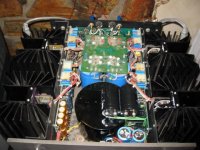
The KMA/KSA is built as three seperate PCBs, one left, one right and the last one at the back of the amp. An enormous transformer and main blue smoothing caps occupies center. Behind the main blue caps is the dc servo//speaker relay etc pcb.
The mods I have described will occur on the left and right PCB's.
The KMA and KSA have the same chassis. No, not hard to dis-assemble.
Unscrew top lid, bottom lid (be careful after this, since amp is now "loose") and rear and front screws
About the mods:
The KMA/KSA is built as three seperate PCBs, one left, one right and the last one at the back of the amp. An enormous transformer and main blue smoothing caps occupies center. Behind the main blue caps is the dc servo//speaker relay etc pcb.
The mods I have described will occur on the left and right PCB's.
I made the following mods to mine:
I added a cascode to the CCS of the input differential amps, and used an LED for their voltage reference instead of a resistor divider.
Used Schottky rectifiers for the regulated power supply.
Used silicon carbide Schottky rectifiers on the unregulated power supply.
Added large heatsinks to the 38V regulators and the servo amplifier.
Added coupling capacitors on the inputs.
Thanks for those JWB.
What were the benefits of the first mod?
Could you post a schematic of your first mod both before and after?
Also, is there any benefit in adding a CCS for the zener voltage references? I've been told that zeners are noisy and that feeding them a constant current helps to reduce this.
Lastly, I did another simple mod which appears to bring further benefit:
For a given channel, the output transistors are mounted on two seperate PCB's. The two PCB's are linked by three thickish wires inside the amp. So the connections are:
Main smoothing caps to 1st output PCB. 1st PCB via three wires to second output PCB.
What I've done is added more smoothing caps (4700uF) between the + and ground and - and ground DIRECTLY on the supply wires (where they feed into the second PCB).
Everything seems slightly louder, which I believe is due to a lower noise floor. Bass also seems to gain additional authority.
to Dr.H
Thanks for Dr.H sharing.
I am curious that replacement:
For the input and voltage gain stage, Krell uses a generic rectifying diode (1n5408) and just 1880uF of capacitance per power rail! I've simply raised this by 10,000uF,
If I change 1880uF capacitance to 10000uF , do you have any recommendation brand or
something I should pay attention to before or after modifications?
Thank you very much.
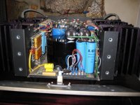
No special caps required, just 10,000uF at 100V.
The Krell KSA/KMA series used a soft start AC circuit so this should help to limit inrush current I guess.
The Krell KSA/KMA series used a soft start AC circuit so this should help to limit inrush current I guess.
Dr.H, when I gained possession of these amps they had both been on fire, therefore I never got the opportunity to listen to them in their original condition. As a consequence I can't really comment on the audible benefits of my changes to the two CCS in the input circuit. Certainly the cascoded CCS with LED reference is better on paper, and in simulation.
Regarding the zeners in the regulated power supplies, both the high and low voltage regulators are quite primitive followers with zener references. There are numerous ways to elaborate on them, with debatable results. Some easy mods would be quieter rectifiers, bigger caps, quieter references, references with lower dynamic impedance, or an entirely different regulator topology.
I like your mod of additional capacitance closer to the output devices. Makes perfect sense to me. Do you happen to have a photo? I find it difficult to imagine where you found the room for the extra caps.
Hi jwb,
Actually not as tight in there as I thought:
The additional smoothing caps for the 100V supply on the inpout stage live ON TOP OF the transformer. I've used short stiff wire, so nor risk of the caps moving or anything.
The additional power supply caps for the output stage live between the front plate and the transformer. They are tall caps, so fit well.
I'll post some pics soon.
PS. The easiest way to do this install is to remove the front plate and top plate and fit the caps.
There is a definite rise in the output volume and the amp is less "fuzzy" on the edges compared with the original .


to Dr.H
What is the improvement of your mods in sound?
Your mods is really great.
do u mod one or a pair amps already?
What is the improvement of your mods in sound?
Your mods is really great.
do u mod one or a pair amps already?
- Home
- Amplifiers
- Solid State
- Reverse engineering Krell KMA 160