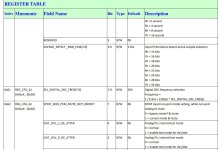
Why choose Mechanical Relay to convert 45M/49M clock!? The speed of Mechanical Relay is slow and is it afraid of the influence of electric field from coil!? We have many options such as 1G125, 1G126 for example...LMK1C1104PWR each for one Clock and use the 2-Pin for enable/disable. Thank youThe principles, component choices, layout advice and a lot more were discussed on this thread:
Some pics of a prototype general purpose DAC Clock board, for which I plan to post the Kicad project. First pic is driving a Andrea Mori FIFO Buffer board; second pic is driving a @MarcelvdG RTZ FIRDAC with asynchronous USB, and reclocking before the dac board (clock board prototype is outlined in red).


The original premise was that the clock board would use 45/49MHz clock modules (or external clocks, including sine wave oscillators using suitable squaring adapters). The 45/49MHz frequencies can be used to externally clock an I2SoverUSB board. The clock...
- Markw4
- Replies: 427
- Forum: Digital Line Level
Markw4 designed the general purpose clock board and the re-clocker/isolation board and made them available to the community. All I did was try to compress the functionality down to fit the amount of space I had left in the case of my already built DAC. In hindsight that was probably a mistake and sticking with Mark's boards would've been easier and ultimately superior, given the other considerations of case layout, spacing between components to reduce crosstalk, etc.
However, I learned a lot from Mark's generous help over many iterations and I believe the v14 board is a reasonable compromise if space is limited.
I will upload the gerbers and BOM once I am happy with the latest misbehaving board but here is the schematic and image of the layout.
View attachment 1384198

A general question. Can we use PCM2DSD to convert all inputs to DSD256 or DSD512 (44.1K family only) endpoints!? Then we only need a single clock, no need for 45M/49M switches... anymore.
Andrea Mori and his colleague Roberto have phase noise measurement equipment. They are aware of clock buffer products. They went with miniature gold-contact relays for switching clocks, probably because they measure best. It would make sense to me. However, I have seen the enable pins on clock buffer chips used for switching clocks lower cost dacs, such as Allo did with their flagship Katana dac.Why choose Mechanical Relay to convert 45M/49M clock...
Also, on the subject of gold plated contacts for low jitter clocks, I learned some time ago not to use tin-plated pin header connectors for that. Only use gold now. Observed degradation of tin contact performance after only one night as contact pressure relaxed over a few hours. Part of it had to do with contact pressure and part has to do with small pitting and corrosion on tin contact surfaces. The main reason gold contacts are used in some applications is to avoid the corrosion effects which can occur with exposure to airborne contaminants.
Last edited:
PCM2DSD is a synchronous converter. It will convert 44kHz family PCM to DSD256/44. It will also convert 48kHz family PCM to DSD256/48. To be able to play content from both clock families requires having two clocks.Can we use PCM2DSD to convert all inputs to DSD256 or DSD512 (44.1K family only) endpoints!?
Last edited:
Hi Marcel,
I've been trying a couple of different PCM-DSD512 software file encoders. When I play back a 16/44 wav file in HQ Player, the audio comes out reasonably good when your PWN FPGA code is running (its not distorted or noisy). When I try to play one of the DSD512 files from HQ Player, there is some music there but its mostly noise and distortion. I'm wondering if the FPGA DSD passthrough mode has the same propagation delay (relative to MCLK, given the reclocker) as when doing the PCM->DSD conversion in the FPGA? Otherwise, I might need to design a selectable dual delay reclocker depending on what encoder/source someone is trying to use. Or, maybe there is some other issue?
EDIT: Thinking about some more, the phase of MCLK going into the USB board is shifted by the PLL. The way I have the delays set, it works with okay with PJotr25 firmware including with external DSD files up to DSD256, and it also works okay with your firmware at DSD512. Its just the DSD512 passthrough that is having a problem.
Mark
Hi Mark,
Does it work properly at lower DSD rates?
Does the level on pin 139 make any difference? The signal "dsdviasd" is on pin 139, it is internally pulled high. When high, a DSD input signal gets filtered and remodulated, when low, a DSD input signal is only resynchronized to the master clock and forwarded to the output (transparent mode).
The output delay is supposed to stay the same and the input is supposed to adjust its timing and automatically sample the data at a suitable moment. I made no assumptions regarding the timing of the master clock other than that it has the right frequency.
I have some code that is only used at DSD512, not at lower input rates. Maybe there is some not yet discovered bug in it.
Best regards,
Marcel
Back side Relay used and selected LMK1C1104PWR to buffer + fanout - this proves that it also has good measurements. So it is possible to use LMK1C1104PWR from the beginning without the Relays. Anyway, I do not like mechanical relays because they have slower response speed.Andrea Mori and his colleague Roberto have phase noise measurement equipment. They are aware of clock buffer products. They went with miniature gold-contact relays for switching clocks, probably because they measure best. It would make sense to me. However, I have seen the enable pins on clock buffer chips used for switching clocks lower cost dacs, such as Allo did with their flagship Katana dac.
Also, on the subject of gold plated contacts for low jitter clocks, I learned some time ago not to use tin-plated pin header connectors for that. Only use gold now. Observed degradation of tin contact performance after only one night as contact pressure relaxed over a few hours. Part of it had to do with contact pressure and part has to do with small pitting and corrosion on tin contact surfaces. The main reason gold contacts are used in some applications is to avoid the corrosion effects which can occur with exposure to airborne contaminants.
Think about some modern component to replace those time-worn flip flop components with a modern component, which has more things in it and where it's all temperature-coupled, for example something like this could replace it for you https://developerhelp.microchip.com/xwiki/bin/view/products/mcu-mpu/8bit-pic/peripherals/clc/ or much better thing like cpld, fpga for example, flip flops is simply not enought for reclocking, expecialy if it is not "one" package. There is a greater chance that your logic cell has the same triggering timing as another cell. It's ridiculous to use flip flop cells that aren't even temperature-dependent with each other with something like the sc pure from Ian, it's a wasted investment in that case to femto clock! It just doesn't go together! Current reclocker spoils your concept.
Metal shielded relays G6K are ok, consider avoiding them because it's much better not to have them in digital.
Metal shielded relays G6K are ok, consider avoiding them because it's much better not to have them in digital.
Last edited:
You don't seem to understand what the reclocking is for. It is not the skew between signals that is critical, but the uniformity of the bit clock periods. When you clock data and the bit clock with circuitry in the same package, you get much more data to bit clock crosstalk due to the common supply and ground wires and the common substrate.
Not a true but ok, but we started a discussion about jitter right? How the ct7302 is not good, it has jitter, phase noise and so on..., not a discussion about the uniformity of the signal, I understand what you mean about uniformity, in that case ok. But even in that case a femto clock doesn't make any sense! I hope you agree with me. I just gave you a few facts about jitter in relation to flip flop, it simply if we talk about jitter does not go together with femto clock. Wrong $250 investment because in that case you can do the same with a $1 XO! Of course it looks more powerful from a marketing perspective, but technically it's definitely a bad investment whether you admit it or not. Then we wonder how a Chinese person can make something for 10 times less money but 10 times better. Let's just be realistic. Nevermind.
Last edited:
When we talk about signal integrity using flip flops, we can safely say that we are not talking about femtoseconds but nanoseconds, in which case this entire mechanism of flip flops with a femtoclock can be replaced with a single stm32, if we are going to be realistic, because we are also talking about nanosecond timings. Let's be realistic! : )
Please have a look at post #1092, https://www.diyaudio.com/community/threads/return-to-zero-shift-register-firdac.379406/post-7419247
Technically speaking, a femtoclock simply doesn't make sense, It's just like that. The rest could be probably obtained with stm32 with a little more work on rcd filtration with a similar result. Everything else makes some sense and I like, but I don't like the idea of a femtoclock specifically in your type of circuit. Maybe I'm wrong, but I just don't see the logic in that right now, don't get me wrong.
Last edited:
I think I'll focus more on the DSC2 DAC, it's simpler and in my opinion better, I'll try a little harder to get a stable 5V on each 8-bit shift register and work a little better on the output frontend and that's it. 🙂
In the next period I'll focus more on the oven and vref, eventualy an driscoll sc cut cristal oscilator in a oven, also the vref will be needed to get a precise 5V. Also I will make a good precision resistor matching tool and this vref will be need too for that too. Nevermind, wish you good luck!
In the next period I'll focus more on the oven and vref, eventualy an driscoll sc cut cristal oscilator in a oven, also the vref will be needed to get a precise 5V. Also I will make a good precision resistor matching tool and this vref will be need too for that too. Nevermind, wish you good luck!
Technically speaking, a femtoclock simply doesn't make sense, It's just like that.
I don't use a 250 dollar crystal oscillator either, just very plain and simple Pierce oscillators with cheap crystals. I do try to minimize data to clock crosstalk, though.
I think I'll focus more on the DSC2 DAC, it's simpler and in my opinion better, I'll try a little harder to get a stable 5V on each 8-bit shift register and work a little better on the output frontend and that's it. 🙂
It depends on the performance parameter. The low-level distortion that is due to idle tones around half the sample rate being converted down to the audio band is some 20 dB worse for the DSC2.5.2 than for the return-to-zero shift register FIRDAC. The sensitivity to the phase noise floor and to (far-off) clock spurious is much better for the DSC2.5.2 than for the return-to-zero shift register FIRDAC.
Nevermind, wish you good luck!
Same to you!
Thanks! It have sense! I noticed that idle tones bug huge while using Amanero too! Even the most time while measuring by osciloscope I notice that when track is stop that Amanero didn't stop their clock! I not like Amanero from that reason and moved to CT usb bridge istead. it is possible to fine-tune mute interrupt based on "silence" bits on dsd bitstream, thats one of the interesting feature in CT and resolution for tunable silence patern is 32bit! Sadly this is only for PCM, but in my case this will be usefull since I going to use two ct7302, first one for anything2pcm than pcm going to dsp and from dsp it going to seccond ct7302 for conversion to dsd, on seccond ct I will be able to fine tune silence patern since from dsp I now have pcm. Just my idea. Digital frontend like that is booth compatible with my ddpd and also for dsc2 and probably for firdac too.
Edit: interrupt should be carefully considered how to do it on complementary gates on ddpd so that no unnecessary silence bitstream goes to the full bridge, but rather that the stream is interrupted based on the mute interrupt, thus avoiding any noise on the full bridge based on silence patern bits.
Edit: interrupt should be carefully considered how to do it on complementary gates on ddpd so that no unnecessary silence bitstream goes to the full bridge, but rather that the stream is interrupted based on the mute interrupt, thus avoiding any noise on the full bridge based on silence patern bits.
Attachments
Last edited:
The ddpd has incomparable dynamics to anything I've had the opportunity to listen to, but I'm not satisfied with how it looks on the measurements, even though I like its sound. While moving to gan concept I double thinking about complementary gates and there also about very precise timing, precise dead time... etc, thats reason why I thinking to do something in relation to precise clocking, squares, as it will be realy needed there. e.g. while on 46V@10A for example : )
Last edited:
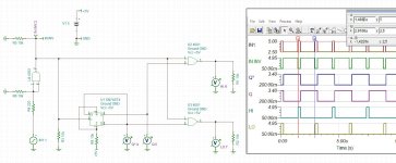
Thinking that phase noise is not very important here but only an clean fully 50:50 square with their stable freq only is need. : ) Freq can be maintained in an fine phase locked oven controler based on frequency but about strictly fine 50:50 squares I curently have no idea how to maintain that precise, even phase locked oven termerature controler is not done yet, just idea. : )
And also there is many of the nice features need to be figured out in CT too! For example CT7601/2 is much flexibile and much complicated than ct7302.
And also there is many of the nice features need to be figured out in CT too! For example CT7601/2 is much flexibile and much complicated than ct7302.
Last edited:
For example clocking must produce something like this, strict 50:50 squares, changing their dutty didn't change 50:50 proportion but only dead time (dutty from 0 to 99.9% in this picture), curenly this gates with flip-flop is not that precise because of propagation delays on each gate which is nanoseccond level, that can't be called precise, this must be done with something much much beter, e.g. an cpld or fpga, in the same time considered an complementary gates function thing which will drive isolated gates in full bridge based on dsd data bitstream which deal with complementary HI-LO and precise dead time between HI-LO.
Attachments

Last edited:
- Home
- Source & Line
- Digital Line Level
- Return-to-zero shift register FIRDAC