Second MY definition of interleaving is this (ignoring the binary weighting in the patent this is sourced from):
View attachment 1330305
I do not see how we get the data to the second FIR DAC delayed by 1/2 clock2f, the second DAC received the same data as the first.
I have no time to give an extensive answer now as I really should go to sleep, but I have added clock2f to the picture. Delaying by half a Clock cycle is equivalent to delaying by a full clock2f cycle. Hence my assertion that the odd and even shift register outputs act as interleaved outputs.
I'm sorta having the issue as Thor. When I look at the output shift registers, sd is clocked into D0 of U14, and into D1 of U16. The signal subsequently simultaneously appears at outputs Q0 and Q1 respectively. Then they next appear simultaneously at Q2 and Q3, respectively (but more or less propagation delayed by one doubled bclk cycle? is that how the interleaving works?).
Last edited:
To simplify matters, I propose to look at the two-tap multibit case first. I hope we can agree that except for a small time shift (and assuming set-up and hold times are met), this circuit produces exactly the waveforms in the patent Thor quoted:


The extension to four taps, multibit is

The "sum odd taps" and "sum even taps" are now RTZ waveforms, as all odd taps return to zero at the same time and all even taps return to zero at the same time. As there is half a Clock cycle (also known as a full clock2f cycle) delay between them, they interleave.
Change multibit into two bit with a funny coding, 01 for +1, 00 for 0 and 10 for -1, and do some tricks to improve matching, and you have my DAC.
The extension to four taps, multibit is
The "sum odd taps" and "sum even taps" are now RTZ waveforms, as all odd taps return to zero at the same time and all even taps return to zero at the same time. As there is half a Clock cycle (also known as a full clock2f cycle) delay between them, they interleave.
Change multibit into two bit with a funny coding, 01 for +1, 00 for 0 and 10 for -1, and do some tricks to improve matching, and you have my DAC.
The above is far too rich for my blood. What I see as far as U14 and U16 are concerned is this.
From the perspective of the output of Q6 data goes in at D0 and 4 cycles later it appears at the output (Q6). The output effectively mirrors the input only 4 cycles later. However, the outputs of the previous 3 flip flops are also tied to Q6 so their outputs also appear at the output of Q6. The output of Q0 appears one cycle later, Q2 two cycles later and Q3 3 cycles later interleaving 3 data outputs between every one that appears at D0. This all assumes the data is clocked in by the associated BCLK.
From the perspective of the output of Q6 data goes in at D0 and 4 cycles later it appears at the output (Q6). The output effectively mirrors the input only 4 cycles later. However, the outputs of the previous 3 flip flops are also tied to Q6 so their outputs also appear at the output of Q6. The output of Q0 appears one cycle later, Q2 two cycles later and Q3 3 cycles later interleaving 3 data outputs between every one that appears at D0. This all assumes the data is clocked in by the associated BCLK.
Deltawave did not show any difference in HF content. Based on the discussion earlier you were desperately trying to discredit Deltawave as you did not understand how it works. If you now understand how it works, please show the HF difference. Otherwise give it a rest.Deltawave showed the original file and one of the copies when compared have a difference in HF content. The difference between the original and the copy can be heard if the difference signal is played back by Deltawave through a reproduction system. Apparently you don't understand how to use Deltawave to compare the original music file and a copy file produced by your DAC/ADC.
Attachments
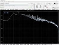

Maybe this simulation of what happens to serial data helps.
The traces from top are:
The LTSpice simulation file can be found from post #2313.
The traces from top are:
- SD (incoming)
- 2nd flipflop Qbar output (U21)
- OR gate output (U19)
- 3rd flipflop output (U22), i.e. data input to shift register
The LTSpice simulation file can be found from post #2313.
Attachments

This all assumes the data is clocked in by the associated BCLK.
The shift register works at the doubled clock. Hence, it shifts at both the rising and the falling edges of the original bit clock. It has to, because its first stage would otherwise either only sample the data, unintendedly converting the RTZ signal back to NRZ form, or only the inserted zeros, producing only silence.
Load both files and press Match as below:Deltawave did not show any difference in HF content. Based on the discussion earlier you were desperately trying to discredit Deltawave as you did not understand how it works. If you now understand how it works, please show the HF difference. Otherwise give it a rest.
Go to the "Play" menu at the top and select "Play Difference." Adjust the vertical volume slider in DeltaWave until you can hear the difference being played back. Its all HF and it sounds ugly. On my system that difference is plainly audible.
Listening to difference amplified tells nothing as masking is missing. Also the difference of waveforms is highly depending on how well the matching is done. Difference of spectra is more telling.
But this was not about if there is a difference. You cockily claimed that the recording "sounds like a muddy, dynamic compressed copy, with lost imaging" when in fact the cause was a 2dB level mismatch.
But this was not about if there is a difference. You cockily claimed that the recording "sounds like a muddy, dynamic compressed copy, with lost imaging" when in fact the cause was a 2dB level mismatch.
That's exactly what the copy sounds like as compared to the original. EXACTLY. The difference in HF content is critical to accurate reproduction, including for imaging in stereo....the recording "sounds like a muddy, dynamic compressed copy, with lost imaging"...
And the difference sure isn't down at -120dB or whatever your measurements claim for your DAC and ADC. Not even close.
Here is what you wrote in post #3151 after listening to 2 copies (one with v4 and the other with v3). According to your later explanation you accidentally used a recording with 2dB lower level for v3.
"St. Louis Blues - 60s-dw1_+2dB_32_nodelay" sounds like the original recording, with the imaging still intact.
"St. Louis Blues - 60s-dw2_+2dB_32_nodelay" sounds like a muddy, dynamic compressed copy, with lost imaging.
So copy with same playback level as the original "sounds like the original recording, with the imaging still intact." while practically the same copy with 2dB lower level "sounds like a muddy, dynamic compressed copy, with lost imaging."
The hole you are digging yourself into is getting too deep so give it a rest.
I know what I wrote, and you know what I wrote next. I explained how I must have accidently clicked on the wrong song in the playlist for one of the files when doing the comparison (the computer is not in front of the speakers, so I have to click on a song then hurry over to the listening position).
When you only quote part of what I said you are by omission deliberately trying to promote a false narrative.
And nothing you say changes the fact that your copies are crappy.
When you only quote part of what I said you are by omission deliberately trying to promote a false narrative.
And nothing you say changes the fact that your copies are crappy.
I quoted your post #3151 exactly as is.
My copies may be crappy according to you but since no one else could tell the difference I don't really care about your claim.
My copies may be crappy according to you but since no one else could tell the difference I don't really care about your claim.
To simplify matters,
You basically claim that the inherent operation of a FIR DAC provides the same result as hardware interleaving using multiple FIR DAC's.
If so, we probably will continue to disagree.
But if that is it, so be it. Call it interleaving, I'm not here to play semantics.
At any extent, I seem to have understand your DAC's operation correctly after all, I just draw a different conclusion.
Your post raised more questions, but I think I will leave it here.
Thor
Can you elaborate why you claim the results would be different? As I see it there should be no difference in theory. Using 2 separate shift registers for interleaving does not necessarily improve anything as device-to-device variations are typically much larger than intra-device variations.You basically claim that the inherent operation of a FIR DAC provides the same result as hardware interleaving using multiple FIR DAC's.
If so, we probably will continue to disagree.
Thor, Marcel seems to be claiming the gross interleaved waveforms over time with his design are the same as if there were multiple DACs producing the interleaving. Marcel?You basically claim that the inherent operation of a FIR DAC provides the same result as hardware interleaving using multiple FIR DAC's.
If so, we probably will continue to disagree.
But if that is it, so be it. Call it interleaving, I'm not here to play semantics.
At any extent, I seem to have understand your DAC's operation correctly after all, I just draw a different conclusion.
Your post raised more questions, but I think I will leave it here.
Thor
If that is correct, then is the question as whether the switching transients (risetime/fall time) are also compensating to the same degree? IOW, the gross waveforms of interleaving over time may be the same, but the subtleties may be different in some important way? Is that the problem?
Mark
For the record: suppose you have two four-tap FIRDACs with impulse response 0.5; 0.5; 0.5; 0.5, with half bit clock cycle delays between the taps. When you just add them, you get 1; 1; 1; 1 with half bit clock cycle delays, when you shift one by half a clock cycle you get 0.5; 1; 1; 1; 0.5.
So even in the ideal case, it's not exactly the same, but if you don't need the second DAC for compensating out systematic mismatches (what I use it for), you might as well cascade it with the first and get one eight-tap FIRDAC with response 0.5; 0.5; 0.5; 0.5; 0.5; 0.5; 0.5; 0.5.
So even in the ideal case, it's not exactly the same, but if you don't need the second DAC for compensating out systematic mismatches (what I use it for), you might as well cascade it with the first and get one eight-tap FIRDAC with response 0.5; 0.5; 0.5; 0.5; 0.5; 0.5; 0.5; 0.5.
So even in the ideal case, it's not exactly the same, but if you don't need the second DAC for compensating out systematic mismatches (what I use it for), you might as well cascade it with the first and get one eight-tap FIRDAC with response 0.5; 0.5; 0.5; 0.5; 0.5; 0.5; 0.5; 0.5.
It was my intention to look at each of these options, that is an 8-Bit FIR or how to create what I consider interleaving with minimum added logic that gives the correct data rippling through both shift registers.
Incidentally, I would argue that the "systemic mismatch" cancellation still operates, as in each BCK cycle we have the same states in opposing polarity across both shift registers, meaning that any mismatch ends up as clock2F current waveform that averages out to zero over a full BCK cycle. At this high a frequency anything needs to be handled by the local decoupling, our regulator will pretty much do nothing at ~12MHz.
The clock doubler precludes using an inverted clock as is commonly done, though where a system clock of > 2 X clock2F is present and used a precise 50% DC clock may be generated with close to precise timing and use that.
Thor
This reminds of something that's rather inelegant in my layout.
For those on this thread who forgot, the idea behind using the same 74LV574A for sd and sdn is that you always have the same number of flip-flops go high, independent of the data.

There is either a pulse at sd or at sdn, so after clocking it into U7, either its Q0 or its Q1 output goes high for one clock2f cycle, and in the next clock2f cycle, either Q2 or Q3 goes high for one clock2f cycle, and so on. If all flip-flops in U7 matched perfectly and the DAC outputs were connected to perfect virtual grounds, this would mean that the supply current of U7 would be data-independent and would only have spectral components at exact multiples of the bit clock frequency. Exact multiples of the bit clock frequency are the only frequencies which do no harm when they end up on the reference supply voltage.
Unfortunately, chances are that the even and odd flip-flops inside a 74LV574A have different on-chip wire resistances (and inductances) to the supply and ground pins, causing a systematic mismatch. U9 is supposed to compensate for that: it has sd and sdn swapped, so when the Q0 of U7 goes high for one clock2f cycle, the Q1 of U9 does the same and vice versa. That is, when you look at U7 and U9 together, the number of Q0's going high and Q1's going high is also data-independent.
This should cancel out any data-dependence of the reference supply current due to different on-chip wiring: when U7 draws a bit too much, U9 draws a bit too little and the other way around, so the sum is data-independent again. However, this assumes that you can combine the supply and ground wires before going to a common decoupling capacitor, and I never managed to do that.
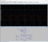
The layout looks like this:

U7 and U9 each have their own decoupling capacitor, and the reference supply is connected symmetrically to those decoupling capacitors. I think you still get cancellation between U7 and U9 to some extent, but it gets sensitive to the matching between the two decoupling capacitors.
Putting one big common decoupling capacitor in the middle would have led to quite asymmetrical wiring: the upper 74LV574A would have a short ground and a long supply wire and the lower 74LV574A a short supply and a long ground wire. Mirroring the devices like I did on the schematic is not possible.
Maybe replacing the 74LV574A with something that has the supply and ground on centre pins could have solved this. The wiring could then be pretty much the same for the upper and the lower part when the decoupling is put between the ICs.
I have absolutely no idea to what extent this would improve performance, if at all. It might help to further improve the low-level distortion, as getting data-dependent rubbish on the reference is one of the ways to get intermodulation products between out-of-band idle tones.
For those on this thread who forgot, the idea behind using the same 74LV574A for sd and sdn is that you always have the same number of flip-flops go high, independent of the data.
There is either a pulse at sd or at sdn, so after clocking it into U7, either its Q0 or its Q1 output goes high for one clock2f cycle, and in the next clock2f cycle, either Q2 or Q3 goes high for one clock2f cycle, and so on. If all flip-flops in U7 matched perfectly and the DAC outputs were connected to perfect virtual grounds, this would mean that the supply current of U7 would be data-independent and would only have spectral components at exact multiples of the bit clock frequency. Exact multiples of the bit clock frequency are the only frequencies which do no harm when they end up on the reference supply voltage.
Unfortunately, chances are that the even and odd flip-flops inside a 74LV574A have different on-chip wire resistances (and inductances) to the supply and ground pins, causing a systematic mismatch. U9 is supposed to compensate for that: it has sd and sdn swapped, so when the Q0 of U7 goes high for one clock2f cycle, the Q1 of U9 does the same and vice versa. That is, when you look at U7 and U9 together, the number of Q0's going high and Q1's going high is also data-independent.
This should cancel out any data-dependence of the reference supply current due to different on-chip wiring: when U7 draws a bit too much, U9 draws a bit too little and the other way around, so the sum is data-independent again. However, this assumes that you can combine the supply and ground wires before going to a common decoupling capacitor, and I never managed to do that.
The layout looks like this:
U7 and U9 each have their own decoupling capacitor, and the reference supply is connected symmetrically to those decoupling capacitors. I think you still get cancellation between U7 and U9 to some extent, but it gets sensitive to the matching between the two decoupling capacitors.
Putting one big common decoupling capacitor in the middle would have led to quite asymmetrical wiring: the upper 74LV574A would have a short ground and a long supply wire and the lower 74LV574A a short supply and a long ground wire. Mirroring the devices like I did on the schematic is not possible.
Maybe replacing the 74LV574A with something that has the supply and ground on centre pins could have solved this. The wiring could then be pretty much the same for the upper and the lower part when the decoupling is put between the ICs.
I have absolutely no idea to what extent this would improve performance, if at all. It might help to further improve the low-level distortion, as getting data-dependent rubbish on the reference is one of the ways to get intermodulation products between out-of-band idle tones.
I think you still get cancellation between U7 and U9 to some extent, but it gets sensitive to the matching between the two decoupling capacitors.
I forgot that at the frequencies of interest, mostly in the megahertz to dozens of megahertz range, the capacitive reactance will be negligible. It would be mostly matching of the parasitic inductance of the capacitors then.
- Home
- Source & Line
- Digital Line Level
- Return-to-zero shift register FIRDAC