BTW, these scope shots are taken at the dac, but right after the DC blocking caps.
Here are a couple with the scope set to hi-res mode:


Here are a couple with the scope set to hi-res mode:
Mark,
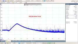
I don´t understand these images when comparing them to my measurements when playing a silent track at DSD256.
See spectrum in the attachment up to 1Mhz, but after Marcel´s analog reconstruction filter.
In your case without this filter, I would expect HF to be significantly more prominent.
Hans
I don´t understand these images when comparing them to my measurements when playing a silent track at DSD256.
See spectrum in the attachment up to 1Mhz, but after Marcel´s analog reconstruction filter.
In your case without this filter, I would expect HF to be significantly more prominent.
Hans
Attachments
Perhaps it would be if measured before the DC blocking caps, and or if all cable and transformer loading on the dac output was removed.
What I don't quite get is why we should care? If the passive filtering as it affects the dac output is effective, then isn't that the goal?
Just keep looking for noise as a sanity check?
What I don't quite get is why we should care? If the passive filtering as it affects the dac output is effective, then isn't that the goal?
Just keep looking for noise as a sanity check?
Last edited:
I have done this test, an RF analyzer on the output of the I/V converter in an AK4499EQ dac.
https://www.diyaudio.com/community/threads/ak4499-noise-at-iv-opamp-output.360714/#post-6355828
https://www.diyaudio.com/community/threads/ak4499-noise-at-iv-opamp-output.360714/#post-6355828
blue & yellow traces are with different modulators, and.. maybe different upsampling rate.. should look up the original notes..🤔
So, you want me to remove the passive output filtering so you can see some noise? I'm not going to listen to it that way...
Neither do I.. active filter stage
But that is the stage (I/V output) where one can observe what are the different DSD modulators really are doing. And what is stressing the I/V circuit, or excite resonances in the passive output filter..
But that is the stage (I/V output) where one can observe what are the different DSD modulators really are doing. And what is stressing the I/V circuit, or excite resonances in the passive output filter..
Last edited:
Also, if the hypothesis is that modulator noise accounts for the perception of space, then how come only changing the upsampling filter but not the modulator changes the space? Does anyone think modulator noise should be a function of the upsampling filter algorithm?
Okay, but what is reflected back to the dac output? Anything that would change the noise there?Neither do I.. active filter stage
should get back ~nothing.. Transimpedance amp, -In is a virtual ground.. (The DAC output node only sees that virtual ground..
the output stage (if opamp with feedback) goes in the low ohm range up to MHzes, towards the next stage
the output stage (if opamp with feedback) goes in the low ohm range up to MHzes, towards the next stage
Mark,Perhaps it would be if measured before the DC blocking caps, and or if all cable and transformer loading on the dac output was removed.
What I don't quite get is why we should care? If the passive filtering as it affects the dac output is effective, then isn't that the goal?
Just keep looking for noise as a sanity check?
I just can’t imagine that the blocking cap etc can change the spectrum to that extend.
But there are two reasons to comment
1) when this spectrum is correct, it means that the digital signal offered to the JLSound’s board is already HF filtered and thus not being a true .dsf signal.
This digital filtering might have impact on the perceived sound reproduction
2) the more HF, the more likely it will interfere with the audio signal because of improper termination of your interlink.
Hans
Do you mean as configured? I mean if you have a discrete resistor dac and you put a big cap across the output then you expect to see some loss of HF at the dac output, right?...when this spectrum is correct, it means that the digital signal offered to the JLSound’s board is already HF filtered and thus not being a true .dsf signal.
In the case of this dac it has a nominal output impedance roughly equal to the the positive phase resistors in parallel. If it were matched to a perfect filter then the filter would look resistive? If not perfectly matched then the passive filter might filter out some frequencies right at the dac output, roughly like putting a big cap there, possibly with some shelving.
Mark,
Yes of course, a resistor and a cap will attenuate HF as a 1th order filter.
But Marcel’s 4th order analog reco filter, starting with the same R-C, will even attenuate a lot more and not less 🤣
So, when your spectrum is showing way less HF as what I measured in #1774 at the output of Marcel’s reco filter, it can only be because the software you are using, that’s offering a signal to the JLSounds board, is doing filtering in the digital domain.
That’s what I meant by saying that it’s no longer a straight but a filtered .dsf file.
And this digital filtering may affect sound perception and also the Frequency Response beyond 20Khz.
Hans
Last edited:
Yes Marcel I know, that’s one of the minus points of 1 bit signals in the audio band, but aren’t there ways to restrict the HF content ?
Or else, how could the low HF content in Mark’s spectra be explained ?
Hans
Or else, how could the low HF content in Mark’s spectra be explained ?
Hans
I also don’t know what Mark is using as a starting point, PCM or DSD?
When for instance the start is with PCM there are several ways to reduce HF like you did with 8 bit PWM.
Hans
When for instance the start is with PCM there are several ways to reduce HF like you did with 8 bit PWM.
Hans
...don’t know what Mark is using as a starting point, PCM or DSD?
Here are some pics playing real music using Simple DSD Converter.
Was I not clear?
The music sounds great. Cymbals sound in normal balance with bass, etc. If the FPGA-based Simple DSD Converter modulator can reproduce real music while not producing any HF noise then it would seem the guys who wrote the firmware must have solved one of the main problems with DSD. However, that seems rather unlikely.
The reason for your subjective preference can be distortion or noise added by PCM2DSD. Without measurements it is not possible to rule that out.
Mark,Was I not clear?
The music sounds great. Cymbals sound in normal balance with bass, etc. If the FPGA-based Simple DSD Converter modulator can reproduce real music while not producing any HF noise then it would seem the guys who wrote the firmware must have solved one of the main problems with DSD. However, that seems rather unlikely.
It wasn’t clear enough to me what these converters are doing.
When using JRiver to convert PCM to DSD, I get a straight .dsf file, but your converter is obviously doing more than that.
I already mentioned Marcel’s 8 bit PWM SDM.
This reduces HF noise significantly but it then deviates IMO from a DSD256 .dsf file.
Hans
Real music is non-PSS. Cymbals don't play constantly nor at a fixed signal level. There is no reason they should show up as a strong spectral line in an FFT?
Besides, the exact same music made from the same wav file sounds pretty close using Simple DSD Converter as it does using two different software based converters. Also have the vinyl of the same music. Mix balance levels of bass and treble instruments are very close to the same no matter how the music is reproduced. Reproduction of sound stage and space is a little different, but the differences are not gross.
EDIT: I will go take a look at it again later to see if I can find any problems. Maybe a problem with how the scope is calculating the FFT, or maybe some other issue not clear at the moment.
Last edited:
- Home
- Source & Line
- Digital Line Level
- Return-to-zero shift register FIRDAC