YesAre these clocks from the same Acko who contributes on this thread ?
The correct clock-family clock for the music sample rate is selected by relays on the FIFO board, then buffered using a low-phase-noise buffer chip. From there, MCLK is output from the FIFO board on a u.fl connector. The signal then goes to the MCLK input on the reclocker board.And the clocks are on the isolator/reclocker, true ?

I wouldn't call that a very similar circuit. In particular, it isn't designed to keep its reference current as data-independent as possible. My DAC is designed to draw an almost data-independent current from its reference that only has spectral content at the bit clock harmonics to make it far less dependent on the reference decoupling (although Mark's filter changes spoil that to some extent). The decoupling of the DAC in the link is also different and the reference regulator is not on the same board as the DAC.My experience is opposite though I don't use X5R. Here is a recent example of what happens with film (or C0G) as bypass caps in a very similar circuit:
https://www.diyaudio.com/community/threads/the-best-dac-is-no-dac.273474/post-7423065
Last edited:
Yes, that occurred to me too. Was thinking about possibly putting a dummy load on the inverted phase outputs to help keep the current draw more balanced....Mark's filter changes spoil that to some extent...
Very similar in the sense that the function of the IC is the same. But my point was that presumably good capacitors for audio are not automatically good decoupling caps. I have not seen many IC manufacturers recommending other than X7R (or maybe X5R) for decoupling.I wouldn't call that a very similar circuit. In particular, it isn't designed to keep its reference current as data-independent as possible. My DAC is designed to draw an almost data-independent current from its reference that only has spectral content at the bit clock harmonics to make it far less dependent on the reference decoupling (although Mark's filter changes spoil that to some extent). The decoupling of the DAC in the link is also different and the reference regulator is not on the same board as the DAC.
BTW regarding decoupling why do you use a trace for connecting U7/U9/U14/U16 GND pin to ground plane?
Yes, that occurred to me too. Was thinking about possibly putting a dummy load on the inverted phase outputs to help keep the current draw more balanced.
Good idea. I did the same with that single-ended DAC I sent you a PM about. It was quite effective, especially during silence.
Hans,Where is this made, already in thr Fifo...
When the FIFO board firmware is configured for RTZ mode, then the BLCK output of the FIFO board is automatically doubled.
The firmware config app kind of looks like this, depending on the mode (without the orange boxes, that is):
It seems Andrea's day job is as a software consultant. He has produced a versatile set of capabilities for the FIFO board and its ability to support a variety of dac types and operational modes.
Mark
Very similar in the sense that the function of the IC is the same. But my point was that presumably good capacitors for audio are not automatically good decoupling caps. I have not seen many IC manufacturers recommending other than X7R (or maybe X5R) for decoupling.
When I design something that requires a 10 cent external component at work, I better have a very good explanation why such an expensive external part is really needed. A 10 euro external component would never be accepted.
BTW regarding decoupling why do you use a trace for connecting U7/U9/U14/U16 GND pin to ground plane?
The idea behind it is to reduce the mutual impedance between the loop formed by the decoupling capacitor and shift register and other circuitry using the same ground plane, by connecting the loop formed by the decoupling capacitor and shift register to the plane at only one place. You would need to try different layouts or do EM simulations to find out if it really works, I did neither. At high frequencies, the return current in a plane always flows below the forward current path anyway, but that's not necessarily the case at lower frequencies.
Just to clarify, the use of these OCXO clocks here are incidental and nothing to do with anything between Mark and myself, or my contributions to this thread. Mark took a calculated risk buying these expensive units based on measured data and found they sound really good as well. I remain committed to an objective outcome from all the tests so that we can make an informed decision going forward…Are these clocks from the same Acko who contributes on this thread ?
And the clocks are on the isolator/reclocker, true ?
Hans
True if you're going to make thousands of devices. However, if its for one critical-to-your-company measurement or QA instrument that you are designing, and which there will only ever be one of, then an extra $40 may be pretty much nothing.A 10 euro external component would never be accepted.
BTW, in my line of work before I retired, an external component could sometimes cost four to six figures. Nobody would bat an eye, depending. They knew how much some of that stuff costs.
Last edited:
Hans,Is there anything to comment ?
Not yet but further changes are coming, as DSD256 hasn't been tried yet with crystal RTZ.
Also, would just say I though the whole hookup was pretty clear from everything I had written and from pics posted so far. Maybe I am too close to it to know how hard it can be to put all the various pieces of information together into a coherent picture.
Mark
True if you're going to make thousands of devices. However, if its for one critical-to-your-company measurement or QA instrument that you are designing, and which there will only ever be one of, then an extra $40 may be pretty much nothing.
BTW, in my line of work before I retired, an external component could sometimes cost four to six figures. Nobody would bat an eye, depending. They knew how much some of that stuff costs.
The context of bohrok2610's remark and my reply to it was integrated circuit design for consumer products. That is, many millions of devices rather than a mere few thousands or even less.
Hans,...now I know exactly what you are doing.
Maybe its a good thing to have information consolidated. What I worry about is if people jump to summary information without following along with the thread, then they may not understand all the details about power wiring, shielding, etc., that are potentially important factors for good results (in addition to what is shown in a basic signal flow diagram). You know.
Mark
Hi all,
I can see that my measurements on the NoDAC I have been experimenting with have been referred to by bohrok2610 (https://www.diyaudio.com/community/threads/the-best-dac-is-no-dac.273474/post-7423065) and commented on by others here.
Just a bit of clarification: I am well aware that the combination of a 470uF capacitor (also with PCM7.5 - high inductance) with a 1210 C0G is not technically optimal but combining listening tests with measurements (on the Vref and on the balanced output) this is the best I have so far been able to come up with sound-wise (there may of course be a better solution that I have not found).
I have also been listening to the Rubycon MU (2.2uF 1210 version, two weeks burn-in with FM radio signal as they apparently are very sensitive to burn-in time) on more occasions, yet to my ears their sound is slightly bright and "shimmery" so I have omitted them again - even if the noise spectrum on the Vref shows a much reduced level at least at DSD128. Also, I have tried various (combined) values of C0G capacitors on the Vref (33nF, 68nF, 120nF & 220nF) in parallel with not too low impedance electrolytics (22uF & 82uF, 0.2 & 0.1ohm) and the 470 uF electrolytic ... Even if some of these combinations lead to lower noise on Vref it doesn't necessarily lead to lower distortion (typically more dispersed noise peaks in the FFTs for combined C0Gs).
As it is I would really like to be able to use something like X5R, X7R, tantalum, polymer, or the like with high volume capacity but so far I have not been able to find any that (importantly: to my ears) also sound good in all respects, i.e. tonality with resolution, spaciality, tempo/speed, bass with resolution etc., etc.
My personal guess is that this is one of the main challenges with both R2R and these discrete DSD DACs. Since they PSU-wise couple directly to their decoupling capacitors it seems to me that these capacitors' sound imprint is quite audible. Maybe a very wide-band & small shunt PSU without decoupling capacitors and with a wide-band low output impedance might be an option ..
Just my two cents on this.
Cheers, Jesper
A P.S.: I reckon Marcel has thought about this, so ... but regarding the phase noise of the clock doubler would it be an idea to replace the 74LVC2G86 with an NC7SZ86 (single bit) or NC7WZ86? Don't know how ease it is to fit them into the PCB, though (haven't checked this - just a thought right now) ...
Jesper
Jesper
P.P.S.: I will be off on a short vacation so just FYI I won't reply in the next ~10 days.
Cheers, Jesper
Cheers, Jesper
I only looked at timing and made sure that the edges that clock the shift registers are not derived from the RC filtered clock signal (only the falling edges of the doubled clock depend on the RC filter). It could very well be that some other logic family produces a lower phase noise floor and/or less 1/f noise.
Mark,Hans,
Maybe its a good thing to have information consolidated. What I worry about is if people jump to summary information without following along with the thread, then they may not understand all the details about power wiring, shielding, etc., that are potentially important factors for good results (in addition to what is shown in a basic signal flow diagram). You know.
Mark
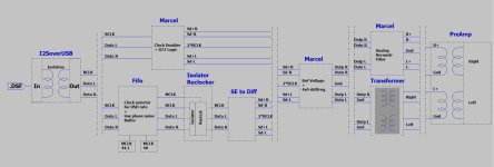
I can still go into more detail when you prefer, like adding power supplies, shielding and details about your transformer circuitry at the Firdac’s output.
To me, by making this diagram, many pieces of the puzzle fell into its place.
A picture tells sometimes more than a thousand words.
I’m still interested in more detail from the Fifo, maybe the picture can help.
The two other Andrea’s boards are no longer a secret, and all of Marcel’s circuits are perfectly documented.
And the suggestion that Andreas Firdac works on a fixed frequency is also worth checking for better understanding when comparing things.
Hans
- Home
- Source & Line
- Digital Line Level
- Return-to-zero shift register FIRDAC