Hm.. in the link the problem was connected to a parallel application of a high Q low ESR & low capacity bypass cap (C0G) + a relatively high ESL, high value electrolytic.. which happily form a resonance peak in their combined impedance. 470uF >> 220nF is not the recommended 10:1 or lower capacity spacing... it's 1000:1
Aand the problem popped up only at given certain frequencies, excitation.
If this kind of resonance is dealt with, or avoided by luck, PPS & acrylic capacitors ~offer much better voltage coefficient, thermal stability, microphonic sensitivity. Only aspect I noticed recently is a more elevated D (lower Q) with respect to C0G.
Last edited:
In Mark's application it's not 100nF which creates resonances.. it's 22uF (real), or ~100uF equally distributed in an (electrically) short range..
actually it is possible to insert a VNA test point (like on the PS pins of the actual 'client' chips) and excite/ monitor the actual impedance curve on the board..
actually it is possible to insert a VNA test point (like on the PS pins of the actual 'client' chips) and excite/ monitor the actual impedance curve on the board..
Last edited:
I've had a similar issue with AK4493 Vref where 100nF C0G bypass increased THD by several dBs. Replacing it with 100nF/100V X7R cured the issue. In this case it was probably not about resonances as the only other cap on Vref was a 10uF X7R.
But it is easy to verify with measurement whether or not the PPS/acrylic bypass causes issues.
But it is easy to verify with measurement whether or not the PPS/acrylic bypass causes issues.
X5R cap that was removed measured 21uf, .09R @1kHz ESR
Film cap measured 22uf, .07R @1kHz ESR
Not a huge difference by that metric.
EDIT: The other thing I would like to say is that not every audible effect shows up well using typical spectral analysis. Therefore spectral analysis shouldn't the only factor that is considered to be important.
Film cap measured 22uf, .07R @1kHz ESR
Not a huge difference by that metric.
EDIT: The other thing I would like to say is that not every audible effect shows up well using typical spectral analysis. Therefore spectral analysis shouldn't the only factor that is considered to be important.
Last edited:
Was this digital or analog, because I'm talking about analog circuitry.My experience is opposite though I don't use X5R. Here is a recent example of what happens with film (or C0G) as bypass caps in a very similar circuit:
https://www.diyaudio.com/community/threads/the-best-dac-is-no-dac.273474/post-7423065
Hans
Mark, with ceramic multilayer caps voltage dependent derating is important. There should be the target DC applied accross the cap while measuring it.. The film capacitor will not change it's valueX5R cap that was removed measured 21uf, .09R @1kHz ESR
Film cap measured 22uf, .07R @1kHz ESR
Not a huge difference by that metric.
True. However, the dac circuit operates at only 5v....with ceramic multilayer caps voltage dependent derating is important.
More like this:
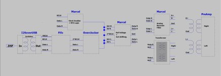
I2SoverUSB -> Simple DSD Converter -> Andrea FIFO Buffer -> Andrea I2S Reclocker board -> Andrea I2S SE to Differential board -> Marcel dac shift register digital inputs -> Marcel dac board SE analog outputs -> Passive filtering -> line amp w/volume control -> power amps -> Speakers
Also, Marcel dac pre-shift register digital circuitry has been disconnected from shift register digital inputs.
Mark,
Of course Marcel’s clock doubler and RTZ logic is not in parallel with Andea’s overclocker board it’s one or the other, I could have placed a switch but thought this was obvious.
But I will add the switches.
The Overclocker also has the differential outputs as can be seen in the diagram, this is one and the same board, true ?
So I think it’s pretty complete, agree ?
Hans
I'm not sure what "this" refers to. I use 100nF/100V or 1uf/50V X7R bypass caps on digital ICs as well as opamps. On Marcel's Vref I have 22uF/16V X7Rs. Clock doubler PS has 10uF/25V X7Rs. Occasionally I have tested C0G, tantalum (solid or polymer) and PPS/acrylic bypass caps without any benefits in sound or performance.Was this digital or analog, because I'm talking about analog circuitry.
Hans,
It looks like this with an isolator/reclocker board and then a SE to differential board:

EDIT: the only difference from the pic above is that the shift register bypass caps were changed as an experiment to see how much it might affect the sound. Turns out it affected the sound quite a bit for the better, but its still not perfect.
Also, the film caps sound went through some changes during the first few/several hours of use. At first they were kind of interesting as I previously described. Then they got kind of muffled and dynamically flat for awhile. Now they are probably pretty much settled in. The sound right now is brighter, less full and warm in the midrange, still pretty good imaging, and dynamics are better than they were. Remaining problem is there is still a little bit of unpleasant HF grunge to the sound. Could be better filtering would help that. Could also be an issue with the Vref power supply, and or with particular choice of shift register devices and output resistor types. Could be its all of those things. IMHO and IME its very hard to perfect everything to the point where you can compete with the best commercial dacs. They have been working on perfecting their stuff for a long time, some of them have anyway.
It looks like this with an isolator/reclocker board and then a SE to differential board:
EDIT: the only difference from the pic above is that the shift register bypass caps were changed as an experiment to see how much it might affect the sound. Turns out it affected the sound quite a bit for the better, but its still not perfect.
Also, the film caps sound went through some changes during the first few/several hours of use. At first they were kind of interesting as I previously described. Then they got kind of muffled and dynamically flat for awhile. Now they are probably pretty much settled in. The sound right now is brighter, less full and warm in the midrange, still pretty good imaging, and dynamics are better than they were. Remaining problem is there is still a little bit of unpleasant HF grunge to the sound. Could be better filtering would help that. Could also be an issue with the Vref power supply, and or with particular choice of shift register devices and output resistor types. Could be its all of those things. IMHO and IME its very hard to perfect everything to the point where you can compete with the best commercial dacs. They have been working on perfecting their stuff for a long time, some of them have anyway.
Last edited:
“This” referred to your different experience.
It was not obvious to me from the link you gave.
Hans
It was not obvious to me from the link you gave.
Hans
Nobody has said that. However for assessing the possible negative impacts (e.g. elevated distortion or noise) listening test alone is not sufficient.The other thing I would like to say is that not every audible effect shows up well using typical spectral analysis. Therefore spectral analysis shouldn't the only factor that is considered to be important.
O.k. So instead of one board there are two boards.Hans,
It looks like this with an isolator/reclocker board and then a SE to differential board:
View attachment 1206357
That’s one of the reasons I made this diagram to better understand what you are doing.
It means that the Fifo board is not in the picture.
I will change the diagram accordingly.
Hans
This will alway be a controversial topic.Nobody has said that. However for assessing the possible negative impacts (e.g. elevated distortion or noise) listening test alone is not sufficient.
Which of the two prevails testing or listening, and who will be the judge of it.
Mark is clearly reporting what he subjectively prefers and nothing else.
Hans
FIFO board and USB board are behind separate shielding. They look like:

Big board with all the connectors and chips is the FIFO board.
USB board (sans Simple DSD Converter in this pic) is shown partially on the lower right.
Clock inputs to FIFO board come in through connectors on the lower left.
Clocks at the moment are Acko Labs AKX-22.
Big board with all the connectors and chips is the FIFO board.
USB board (sans Simple DSD Converter in this pic) is shown partially on the lower right.
Clock inputs to FIFO board come in through connectors on the lower left.
Clocks at the moment are Acko Labs AKX-22.
Are these clocks from the same Acko who contributes on this thread ?
And the clocks are on the isolator/reclocker, true ?
Hans
And the clocks are on the isolator/reclocker, true ?
Hans
Not always. If I prefer something then I try to say its a preference, or that I like or dislike it.Mark is clearly reporting what he subjectively prefers and nothing else.
OTOH if I say 'S' sounds like 'Sh' I am not trying to express a preference for one or the other sound. I just want it to be the correct sound that is on the recording. Not every 'S' on every recording was probably recorded to sound like 'Sh.' Therefore I may suspect there is a problem if I hear something like that on every recording.
Not really. E.g. the difference in noise of Marcel's dac measured by you and me is not audible but it is measurable.This will alway be a controversial topic.
- Home
- Source & Line
- Digital Line Level
- Return-to-zero shift register FIRDAC