The more important is that you have provided pads to add or not a bas stopper. It can be any value from 0r0 (link) to 10r.
You also have provision for base stopper on the drivers.
You also have provision for base stopper on the drivers.
yes .i have a new pcb made with the provision of adding base stopper resistors on drivers and output transistors or just jumpers if not used,but i dont know what values to choose.
are 68 ohm for drivers (2sc4793-2sa1837) and 4.7ohm for output(2sc5200) enough? how are the values choosen?
are 68 ohm for drivers (2sc4793-2sa1837) and 4.7ohm for output(2sc5200) enough? how are the values choosen?
drivers any where from 0r0 to 100r
outputs any where from 0r0 to 10r
depends on the stability margins.
outputs any where from 0r0 to 10r
depends on the stability margins.
The old Motorola app note AN-483B shows what can be accomplished with very simple circuits and darlington outputs. Worth a read in relation to this. Sorry my copy isn't a bit cleaner. The old RCA transistor handbook has application circuits in the back along the same lines. I've built amps from both sources and they performed well, at least sonically. Today I'd be following the designs from Doug Self and Bob Cordell.
AN-483B
AN-483B
If you are interested in old style amps you may want to invest in old style magazines. Back issues of Audio Amateur from the 70s are available on the web:
The Audio Amateur on CD-ROM: 1970-79 - Circuit Cellar, Inc.
and include many construction articles. I have a Williamson 20-20 from a 1970 construction article that is doing fine after well over 30 years use.
The Audio Amateur on CD-ROM: 1970-79 - Circuit Cellar, Inc.
and include many construction articles. I have a Williamson 20-20 from a 1970 construction article that is doing fine after well over 30 years use.
dear maouna,
Have you seen the thread http://www.diyaudio.com/forums/solid-state/205041-jlh-dinsdale-amplifier.html ? You may try the type of compensation used by JLH instead.
--gannaji
Have you seen the thread http://www.diyaudio.com/forums/solid-state/205041-jlh-dinsdale-amplifier.html ? You may try the type of compensation used by JLH instead.
--gannaji
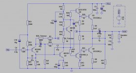
Interesting maouna. Is C1 miller effect compensation? When dynaco put something like that on their ST120 in the "TIP mod" (see greg dunn's site) I thought it was for preventing oscillation. I've put a 50 pf on per dynaco, seems to work fine. At least they may have been 50 pf. they were R**** S**** grab bag caps, red black brown, looked to be two curls of wire glued to the end of a 1 cm cardboard tube.
C3 I guess is the feedback cap.
R9 could be fine but if the wiper lifts could cause an output stage bias runaway. Better to put a trimpot parallel to R16, with wiper shorted to one end, then if the wiper loses contact the bias goes high but not infinite.
C3 I guess is the feedback cap.
R9 could be fine but if the wiper lifts could cause an output stage bias runaway. Better to put a trimpot parallel to R16, with wiper shorted to one end, then if the wiper loses contact the bias goes high but not infinite.
Last edited:
C1 is miller compensation cap and C3 is feedback cap.About R9,if wiper lifts the output stage will just get underbiased.no problem.
Hello, everybody!
This amp looks nice, can we have the PCB mirror image, and dimensions?
And capacitor below 2SD1837 is not connected, I suppose it must be connected to base pin of transistor below?
Can this amp work with TIP3055 as output?
This amp looks nice, can we have the PCB mirror image, and dimensions?
And capacitor below 2SD1837 is not connected, I suppose it must be connected to base pin of transistor below?
Can this amp work with TIP3055 as output?
Hello, everybody!
This amp looks nice, can we have the PCB mirror image, and dimensions?
And capacitor below 2SD1837 is not connected, I suppose it must be connected to base pin of transistor below?
Can this amp work with TIP3055 as output?
http://www.diyaudio.com/forums/solid-state/236256-retro-amp-50w-single-supply.html
Use BD911 instead 2SC5200 for 50W
I have some BD249C. Can they be used as well?
Member
Joined 2009
Paid Member
Hi Maouna,
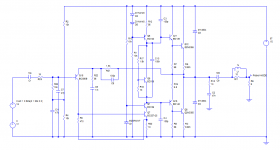
You might be interested in what Gannaji is planning to do - he's looking at a simple version of my TGM8 amplifier with singleton input, single rail power supply and the promise of very good sound. It will be a through-hole pcb design and depending on how much interest from Gannaji I would be interested to help.
You might be interested in what Gannaji is planning to do - he's looking at a simple version of my TGM8 amplifier with singleton input, single rail power supply and the promise of very good sound. It will be a through-hole pcb design and depending on how much interest from Gannaji I would be interested to help.
Hi.Yes i would like to try this combination of singleton input,Vas bootstrap and Sziklai output. I will be watching your thread TGM8 - an amplifier based on Rod Elliot P3a
Hi,
You might also consider PSRR. These old amps with a single supply have everything refered to the 0V rail. The + rail is protected by the bootstrap. As a result, coupled with the current amp config, I am not sure they don't work better than 'modern' direct coupled designs. The Armstrong 621 circuit is my favourite. A bit more complex but with better performance.
You might also consider PSRR. These old amps with a single supply have everything refered to the 0V rail. The + rail is protected by the bootstrap. As a result, coupled with the current amp config, I am not sure they don't work better than 'modern' direct coupled designs. The Armstrong 621 circuit is my favourite. A bit more complex but with better performance.
That Miller capacitor again!
If you use a current source in the VAS, and inclusive Miller feedback the crossover distortion can be reduced significantly. The input bias circuit tends in my experience to cause low frequency noise (depending on the source impedance) and a better solution is to use a divider circuit across the supply, tapped at the mid point, decoupled with a medium capacitor and a 10k resistor taken from there to the base.
A Baxandall diode may not be needed with a current source and the emitter resistor of the pnp driver could be 6.8 ohms without a diode bias.
I wouldn't recommend 2N3773's. Modern versions MAY be epi-base but the spec. hasn't changed - fT could be 200kHz. Yuk! Epi 3055's have fT's around 3 MHz- OK for basic amps.
The best bet for single ended input transistors is to use inclusive feedback (see Bailey's 1968 complementary amp in Wireless World) where the feedback capacitor of about 220pF is taken from the collector of the VAS to the emitter of the pnp input. This may be unstable with a high frequency BC556 in the input (Bailey used a 40361 but that has a lower fT) which can be fixed with a small capacitor (~100pF) between base and ground to keep the impedance low at high frequencies.
John
- Status
- Not open for further replies.
- Home
- Amplifiers
- Solid State
- Retro amplifier 50 watt circuit