Thanks LKA for the test results. Sub .002% HD . My ears said my AX6 was great but it is nice somebody has instruments to measure it.
I suppose by tuned you mean matched Vbe of output transistors? Or did you match gain? Did you have to match the drivers? What 6 transistors did you use? The input and VAS appear to be TO-126 instead of TO-92.
I suppose by tuned you mean matched Vbe of output transistors? Or did you match gain? Did you have to match the drivers? What 6 transistors did you use? The input and VAS appear to be TO-126 instead of TO-92.
Last edited:
Input stage, single to92
Enchanced VAS, two to92, bootstrapped load
VAS buffer, single to126
Vbe multiplier, single to126
2EF output stage, driver idle 9mA, output idle 3mA
3 pole compensation, 90dB loopgain at 10kHz
Enchanced VAS, two to92, bootstrapped load
VAS buffer, single to126
Vbe multiplier, single to126
2EF output stage, driver idle 9mA, output idle 3mA
3 pole compensation, 90dB loopgain at 10kHz
Nine transistors not an AX6. Gannaji is right, please start a new thread with a schematic diagram & post your excellent results there.
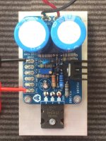
Tuned retro amp (AX6 alike) measurements. Single supply, 75W/4R, class-b, no emitter resistors.
The $64,000 question here is - Is it thermally stable w/o emitter resistors at 75 watts?
I ran it for 30 minutes at half power (maximum dissipation) without any problems.
The quiescent current settled quickly back to 3mA.
The quiescent current settled quickly back to 3mA.
Last edited:
Did you re-measure output stage bias current to see how much it moved?
no, dunno how to measure it. imho it's rock stable and cool, only 33mA quiescent current for whole amp
"Drivers C4793 / A1837 and output NJW0201G / 0302G?"
yes
Not sure if this is the right place to post this. But I see you guys are talking about Power Supply.
Im working on building an amp for myself. And the first step is a good power supply section.
Have been hunting on the web for months. And so far have zeroed in on this design. For my power supply.
It would be fun to have your inputs. Is this a good design. Or should I go with one of the designs here.
Attachments
Seriously Suggest:
Buying/using the DIY store's (in this forum) universal PSU .. PCB and follow the Build guide for it.
It will Not disappoint.
Buying/using the DIY store's (in this forum) universal PSU .. PCB and follow the Build guide for it.
It will Not disappoint.
Hi Prasi,For the compact crc, if you plan on using it on high power, best to use chassis mount rectifiers and connect it to pcb via wires.
PSU 10R , I will ditch them and use on-semi to-264.
PS: I seem to have the exact layout. 🙂
I assembled a PSU10R for a project. However, it doesn't work. The input voltage is output as it is. Where am I doing wrong? The multi-turn pot does not respond.
Attachments
What is your input voltage?
Regulation will start around 45v input. If you need lower, change zener from 15v to 12v and regulation starts around 36v input.
Regulation will start around 45v input. If you need lower, change zener from 15v to 12v and regulation starts around 36v input.

Hi faziladiken,
do the checks as mentioned by avtech.
I couldnt find the post, but someone had the same issue, he changed zener and / or pot to a different value, it worked.
cant remember where...
do the checks as mentioned by avtech.
I couldnt find the post, but someone had the same issue, he changed zener and / or pot to a different value, it worked.
cant remember where...
You need to use a smaller trimmer for those values. The regulation for 50v and 12v zener occurs during R= 0 to 3k:

Hi AvtechYou need to use a smaller trimmer for those values. The regulation for 50v and 12v zener occurs during R= 0 to 3k:
View attachment 1061383
I have a 5k trimpot. I tried it and it worked. I can adjust between +35v dc and 50v dc. What changes should I make to go below 35v dc.
A 9.1v zener with 5k gives 29v-46v regulation.
R9, R8 and R4 (on my sim) need to be 1/2w components. R9 in particular goes to ~320mW when the pot is at max and 12v zener is used, ~290mW with 9.1v zener. 1/4w just won't cut it for that position.
Power dissipation of the semis seems to be well within their tolerance, but as always experiment with component changes at your own risk.
Ac 30 0 30 tranceformer use this?2x36vac 75VA for mono 150VA for stereo.
Which super fast diod yous this pcb?AX-6 Weekend Project
Very nice little amplifier 🙂.
Built and work. Nice warm sound.
regards Olaf
- Home
- Amplifiers
- Solid State
- Retro Amp 50W Single Supply