A little more.
Not butik parts here.
Not butik parts here.
Attachments

Last edited:
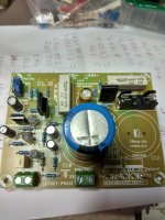
First attempt to play failed.
Only crackling sound, zero bias.
What is the recommented power supply, i had tried using 50v.
Only crackling sound, zero bias.
What is the recommented power supply, i had tried using 50v.
Attachments
Last edited:
Hi thimios, congrats, first off the line. Can I please ask why the zenors are positioned the way they are, is it for easy access. What measurement do you look for there. Thanks, love your work.
I think the schematic (or pcb) said to keep those diodes in contact with the heatsink.
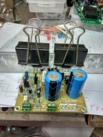
Congrats on getting the build ready to test Thimios! Always disappointing when the board doesn't sing from the start but hopefully it is a simple fix! Any chance of a top-down photo of the completed board?
Cheers
Congrats on getting the build ready to test Thimios! Always disappointing when the board doesn't sing from the start but hopefully it is a simple fix! Any chance of a top-down photo of the completed board?
Cheers
Hi thimios,
1. 50V is perfect.
2. Like Terry said, I dont see jumper installed (its a single sided PCB, so needs jumper).
3. Nice small value caps... retro?
regards
prasi
edit: on a closer inspection, I think I see the jumper installed underboard. post#361 first image.
So the problem could be somewhere else.
1. 50V is perfect.
2. Like Terry said, I dont see jumper installed (its a single sided PCB, so needs jumper).
3. Nice small value caps... retro?
regards
prasi
edit: on a closer inspection, I think I see the jumper installed underboard. post#361 first image.
So the problem could be somewhere else.
Last edited:
Tnank all of you for answers, diodes 2X1N4148 are here bacause this is instead Vbe multipl.
Close contact to heatsink required.
Maybe closer or inside to a drilled hole is better.
Yes Prasi! Eagle eye!!!
Jumper is under the board because putting this on the top affect caps position. This is first ver. PCB and Prasi will see something better in the future.
BTW i can't see any disadvantage using this way.
I will take some underboard pictures latter.
Tnanks again.
I feel that i find the problem now, i amn't near the workstation but as you can see on post#332 a npn symbol represents the 2N5401.
Due to 2N5401 unavailability i used MPSA42.
The Right is a PNP here.
I hope all other will be ok. now.
Last edited:
another observation: There is no need to instal R8 if you already have the trimmer(R8'). Once you finalize the bias, you can instal equivalent resistor in R8 position.
Yes, you are correct thimios, it has to be a PNP here. symbol is wrong in my schematic .
.
Yes, you are correct thimios, it has to be a PNP here. symbol is wrong in my schematic
.
Last edited:
another observation: There is no need to instal R8 if you already have the trimmer(R8'). Once you finalize the bias, you can instal equivalent resistor in R8 position.
Hi Prasi, did you mean... do no instal the fix resistor, instal the trimer, adjust for the bias setting, remove trimer, measure for the value, instal a same value fixed resistor?
Finally what is the recommended bias setting?
Last edited:
Hi Prasi, did you mean... do no instal the fix resistor, instal the trimer, adjust for the bias setting, remove trimer, measure for the value, instal a same value fixed resistor?
Finally what is the recommended bias setting?
Hi thimios, yes, fixed resistor after bias set. Mr. Mile recommended 20mA to 50mA bias somewhere on the thread.
regards
Prasi

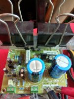
The mistake was on my side when I put a npn symbol in place of a PNP in the schematic.
Take your time, no hurry in this.
Regards
Prasi
Take your time, no hurry in this.
Regards
Prasi
Quickly i can say, yes this amplifier is honest, he just ask low budjet parts except..... For power supply!
That's why Apex recomment cap. mult.
Low very low PSSR. due to single inp. configuration.
In my first attempt hum was audible two rooms far!
Now is silent without cap. mult.
The rest latter.
In any case don't expect good measurments, like square
waves, good clipping e.t.c.
How this play?
I like it!
Isn't the best but it is honest.
Yes i like this safe, cheap, good playing retro.
Congratulations thimios, thanks for your comments. I’ll keep an eye out for the npn pnp mistake. What location is it?
No Prasi it is my mistake,there isn't a NPN trans.with emitter connected to + supply!The mistake was on my side when I put a npn symbol in place of a PNP in the schematic.
Take your time, no hurry in this.
Regards
Prasi
This is a stupid mistake,always i repeat stupid mistakes.😡
BTW someone must delete schematic from post #332 to prevent troubles in the future.
- Home
- Amplifiers
- Solid State
- Retro Amp 50W Single Supply