I'd tend to agree with Wrench... you could try using the outputs with completely new everything else (the NAIM 250 & the Plinius are both quasi-complementary so its not a bad thing), but if you are putting the energy into they should be replaced too ... then you are faced with -- what amp can i build that uses 60v rails and can live mounted to these heatsinks?
dave
dave
TomWaits said:
because I kinda agree here too Wrench. I'm very worried about the output devices. Come on, the PN junctions have got to wear down and start leaking? But that is a little too soon as I will test them to make certain.
I doubt the PN junctions would "wear down" and start leaking, unless they got REALLY hot... doping diffusion in silicon during mfg. requires temps of more than 930 centigrade for significant time... anything THAT HOT in this amp would've done other damage as well... are the cases toasty?
Humpty Dumpty or What?
I'm laughing...now what do I do? I'm screwed! Ha he ha...
 I can do it...don't worry.
Actually it is all trev's (latala) fault. I blame it on him.
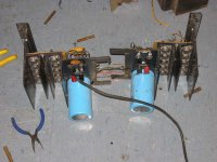
I'm done for the night dismantling but I will clean it up a bit and in the morning I will remove the transistors and the output boards.
Can you folks suggest a test jig for 2N5631?
The output transistors are marked:
M (batwing logo from MOT)
2N5631
Mexico
9348
Going down each bank of 2N5631's in the middle of each row is a TO3 faintly marked
C5869-0
#1
What is the scoop on the middle TO3 with this marking? Perhaps I should look at the schematic now?
The PWR supply caps are marked 17,000uF @ 75VDC
The bridge rectifier is marked
SDA990-3
SI 7519
I'll drop a giant 50Amp unit in?
It is a history lesson. hmmn? 1975? Didn't sales guys drive around with parts in the trunks of their cars selling parts? I've heard stories of drunk sales guys showing up at OEMs with garbage bags of goodies on Friday's @ lunch?
Their must be some truth in it as I head it many times?
CHEERS and back to BEERS!
Shawn.
I'm laughing...now what do I do? I'm screwed! Ha he ha...
I can do it...don't worry.Actually it is all trev's (latala) fault. I blame it on him.
I'm done for the night dismantling but I will clean it up a bit and in the morning I will remove the transistors and the output boards.
Can you folks suggest a test jig for 2N5631?
The output transistors are marked:
M (batwing logo from MOT)
2N5631
Mexico
9348
Going down each bank of 2N5631's in the middle of each row is a TO3 faintly marked
C5869-0
#1
What is the scoop on the middle TO3 with this marking? Perhaps I should look at the schematic now?
The PWR supply caps are marked 17,000uF @ 75VDC
The bridge rectifier is marked
SDA990-3
SI 7519
I'll drop a giant 50Amp unit in?
It is a history lesson. hmmn? 1975? Didn't sales guys drive around with parts in the trunks of their cars selling parts? I've heard stories of drunk sales guys showing up at OEMs with garbage bags of goodies on Friday's @ lunch?
Their must be some truth in it as I head it many times?
CHEERS and back to BEERS!
Shawn.
The output stage could use something like Mj15003s. These are cheap, have higher gain and are faster than the original. There are better TO3's around but the price-performance balance applies.
I've made a list of all the transistors in a table. I'll offer some suggestions soon (FWIW).
Cheers
Q
I've made a list of all the transistors in a table. I'll offer some suggestions soon (FWIW).
Cheers
Q
Heat Sink
The potential power available from this old set up seems to overwhelm the heatsink/chasis set up of this amp??? Perhaps the power supply drops down a large percentage under full load? I will test and provide DC RMS values to see where it sags to.
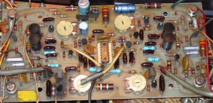
I would love to keep the essence of the Crown circuitry. That is my strongest priority and I want to look at it that way until it is proven implausible. Can we try to keep the restoration of a vintage Crown DC300A alive? I admit it may take some awkward effort but I'm willing to try to preserve and improve. That is my goal and I am certainly willing to make new PCBs if required.
The Quasi folks are here already! It is the weirdest thing how it all came together? Oh well, lets see what happens. BUT I totally see you(Dave) on it and you have a very high chance of being right. As I see it (looking at the surgery on my basement floor) it may be a Humpty Dumpty.
Still, I look forward to keeping it DC300A somehow?
Shawn.
planet10 said:I'd tend to agree with Wrench... you could try using the outputs with completely new everything else (the NAIM 250 & the Plinius are both quasi-complementary so its not a bad thing),
dave
The potential power available from this old set up seems to overwhelm the heatsink/chasis set up of this amp??? Perhaps the power supply drops down a large percentage under full load? I will test and provide DC RMS values to see where it sags to.
I would love to keep the essence of the Crown circuitry. That is my strongest priority and I want to look at it that way until it is proven implausible. Can we try to keep the restoration of a vintage Crown DC300A alive? I admit it may take some awkward effort but I'm willing to try to preserve and improve. That is my goal and I am certainly willing to make new PCBs if required.
planet10 said:but if you are putting the energy into they should be replaced too ... then you are faced with -- what amp can i build that uses 60v rails and can live mounted to these heatsinks?
The Quasi folks are here already! It is the weirdest thing how it all came together? Oh well, lets see what happens. BUT I totally see you(Dave) on it and you have a very high chance of being right. As I see it (looking at the surgery on my basement floor) it may be a Humpty Dumpty.
Still, I look forward to keeping it DC300A somehow?
Shawn.
auplater said:
I doubt the PN junctions would "wear down" and start leaking, unless they got REALLY hot... doping diffusion in silicon during mfg. requires temps of more than 930 centigrade for significant time... anything THAT HOT in this amp would've done other damage as well... are the cases toasty?
I think you're right and any leakage is most likely from the pre and voltage drive sections (problems before). I like the cut of your jib. That is the attitude I'm looking for. However this thing has definitely been tortured and the outputs are certainly original. I got to measure them to see how they are.
Shawn.
Power Supply is Very Good
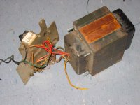
The XFMR measures 54-0-54 VAC unloaded
I rectified it and filtered it through 30,000uF per rail and measured +_ 62 VDC
I loaded each rail down with 10 ohms and measured +_54 VDC @ 5.4Amps per rail. The XFMR did not warm up at all during this test.
I don't have a smaller load to test it with. The back plate of the ransformer says it draws 1200 watts (not VA) I think it is Beastly. This transformer rocks. No humming or buzzing btw.
Shawn.
Re: Power Supply is Very Good
Hi Shawn,
The unloaded DC voltage seems about 10 volts too low. You might want to try that again with a different DC section.
Cheers
Q
TomWaits said:The XFMR measures 54-0-54 VAC unloaded
I rectified it and filtered it through 30,000uF per rail and measured +_ 62 VDC
Shawn.
Hi Shawn,
The unloaded DC voltage seems about 10 volts too low. You might want to try that again with a different DC section.
Cheers
Q
Well i went to bed art 12 last night and now when I wake I find that you are really busy !
The design as you can see is AB/B and cropwn have always quoted distortion figures on this amp in a wierd way! saying it below ? at 50 mW and below ? at 180 watts I suspect a little glitch or so around the 0.5 watt level ?
Can not one of you guyscome up with a current duming type of scheme to get the figures really low
About 30 years ago I produced a large no of AB/B amps for a ocal heavy rock disco using this Idea and when I loaded the amps at about 2ohms the tranfer function could be seen to change as the booster s came on.
I never did clear that one this was a year or so before the Quad 405 was laubched
So I see the Crown Dc 300 as an improved version of that scheme at the time
Please remember for the time these were awsome units
I am over the moon to have got you going on this Tom
And will follow your progress
Lets make this a text book project
Regards Trev
Hi Tomwaits,
I particularly like the IV protection locus printed in the very comprehensive manual.
I would suggest you examine the circuit thoroughly and identify exactly which component values achieve this protection.
It appears to allow a fair margin for reactive loads as well as good short circuit current and has integrated the fusing into overall longterm protection.
There is one area that may be worth altering. Try to find the time constant that allows transient output current to pass without triggering the protection too early. This may improve sound quality by avoiding the fixed DC triggering levels affecting very short term signals that generally do not cause any risk to the output stages.
The amplifier is obviously well specified as an 8ohm +8ohm capable unit. I might look at using the update as an opportunity to design in 4ohm capability (needs altering that protection locus) allowing 2r testing in lieu of the 4r stated in the document. You could also (space permitting) dual the PSU (from the single transformer) to give more independant working between the channels. Have a look at the Definitve earthing thread:- pic of the Naim for a compact dual PSU.
edit:-
the 15003 are seriously compromised at the supply voltages available from this amp. 21193 would be much better in the higher voltage region of SOAR. The extra current from the 15003 is of no advantage.
BTW. 4pair of 21194 can go to well above 500W into 2ohm at a phase angle of about 40degrees (way above the halved test load used by Crown).
Re: Re: Power Supply is Very Good
Oops, my typo.
The VAC from the XFMR unloaded is 45-0-45 VAC
+_ 62VDC rectified and filtered
+_54 VDC @ 5.4Amps per rail with 10 ohm resistors on each rail.
There are no other taps on the transformer.
The schematic shows +_65 VDC rails.
Shawn.
TomWaits said:The XFMR measures 54-0-54 VAC unloaded
quasi said:...The unloaded DC voltage seems about 10 volts too low. You might want to try that again with a different DC section...
Oops, my typo.
The VAC from the XFMR unloaded is 45-0-45 VAC
+_ 62VDC rectified and filtered
+_54 VDC @ 5.4Amps per rail with 10 ohm resistors on each rail.
There are no other taps on the transformer.
The schematic shows +_65 VDC rails.
Shawn.
Hi Tomwaits,
when you measured the Vac on the secondary, what was the Vac on the primary?
When Crown quote 45Vac, what do they feed in as mains voltage?
What is your normal mains voltage (averaged over the times when you habitually listen)? It makes a big difference to absolute power but little difference to SPL levels.
AndrewT said:Hi Tomwaits,
when you measured the Vac on the secondary, what was the Vac on the primary?
116Vac Measured at the leads on the XFMR
Should be 120 and I measure any where from 116 to 119 as it varies from outlet to outlet in this 100 year old shack. 😉
Shawn.
Hi Tomwaits,
those measurements just about confirm why +-62Vdc rather than +-65Vdc. So all is OK with the transformer, rectifier and smoothing.
those measurements just about confirm why +-62Vdc rather than +-65Vdc. So all is OK with the transformer, rectifier and smoothing.

Insulators are hard-anodized aluminum, do not scratch.
Original outputs are epitaxial 2N3773, 150W SOA at 100V. Do not use 2N5631 or MJ15003, the MJ15024 or MJ21194 are fine.
Original main filter caps were 13,500µF at 75V, and ran at ±67V.
The 10µF filter cap in the voltage doubler circuit goes bad all the time, also replace the current source transistors in this circuit. The zener diodes that power the µA739 frequently fail.
Crown has always used inductors in the base circuits to reduce oscillation, even in their newer amps.
While there are some good sounding quasi-comp amps (Altec 9440A comes to mind), the Crown is not one of them. No matter what you do, this amp will sound 'bright'. The phrase 'broken glass' comes to mind.
While there are some good sounding quasi-comp amps (Altec 9440A comes to mind), the Crown is not one of them. No matter what you do, this amp will sound 'bright'. The phrase 'broken glass' comes to mind.
The ONLY thing in favor of the Clown DC300 is it makes a good boat anchor.
Please take it out in the country and either bury it or shoot it. Put it out of its misery at any rate. Not a good amp when new unless you listened to it drunk or you were hard of hearing and tone deaf.
The Altec 9440 on the other hand will outshine a lot of the newer amps.
You guys must be bored to death..... please try something else to waste your time....

- Home
- Amplifiers
- Solid State
- Resurrecting a Crown DC300A