Your correct Chris, compensation yes.
The 5532 is a dual op amp 8 pin. The 5534 unless I am mistaken is a quad op amp.
Shawn,
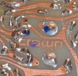
Nice pictures. What is the board number?
Date code of 1993 on those outputs.
The 5532 is a dual op amp 8 pin. The 5534 unless I am mistaken is a quad op amp.
Shawn,
Nice pictures. What is the board number?
Date code of 1993 on those outputs.
Your fast SY
I was trying to edit it to single when you posted.
INTRODUCTION.
The 5534 is a low-noise, low distortion bipolar opamp. The 5532 is a dual 5534 with compensation set internally for unity-gain stability.
The major features are:
The bipolar input devices give their best noise performance at low to medium impedances, in the range 100 - 1000 Ohms. In virtually all audio applications the 5532 will be quieter than the TL072.
Bipolar input devices, with significant bias and offset currents.
The common-mode range of the inputs is a healthy 13V, with no phase inversion problemsif this is exceeded.
The input pins are tied together with diodes for reverse-Vbe protection. This is normally unnoticeable in audio use, but it does mean the 5532 makes a poor comparator.
Very low, though not quite zero, THD levels. THD still depends on how heavily the output is loaded.
Higher power consumption: approx 4mA per opamp section. The DIL version runs perceptibly warm when quiescent on 15V rails.
Requires proper rail decoupling near the chip.
9555
Sorry, I meant to get to that earlier. 😉
9555
Cheers,
Shawn.
burnedfingers said:Shawn,
Nice pictures. What is the board number?
Date code of 1993 on those outputs.
Sorry, I meant to get to that earlier. 😉
9555
Cheers,
Shawn.
Attachments
uA739
I'm going to use uA739DC on my first time around. I'll be sending some quid to krmaudio in a day or two to hook up with the ceramic option.
I'm very interested in substituting this opAmp with better technology so I'm listening very hard.
The machined T&B 14pin dip socket I have has a decoupling cap across 14 & 7 of the rail supply. Should I disable it or will it be fine running in this design?
Shawn.
Attachments
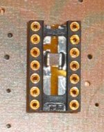
Decoupling will be fine. Pin 7 and 14 are the B+ and B- supplies.
Getting back to schematics.... If you need copies let me know and I will take the manual to a copy shop and have them make you some readable copies. The scanner here does ok but at our age its nice to have better detail.
Getting back to schematics.... If you need copies let me know and I will take the manual to a copy shop and have them make you some readable copies. The scanner here does ok but at our age its nice to have better detail.
burnedfingers said:Getting back to schematics.... If you need copies let me know and I will take the manual to a copy shop and have them make you some readable copies. The scanner here does ok but at our age its nice to have better detail.
Wow! It would be nice to see some other variations but I'd be on the hook for something? Could you tell me a bit more about your manual? Does it cover the amplifier better than the old scan on the Crown Site? If it does, I may be very interested and paying for those scan fees (and postage if not a digital scan).
This is what I have been using as my guide. It does not have the procedures to adjust the offset and set the "wild card" resitor values of R107 & R207, as one example.
Right now I'm soldering components into my new driver boards as I just finished drilling it out on the press. 😀
Cheers,
Shawn.
Taking pictures...
Tripod = 4 foot high TL speaker
distance = 3~5 feet from object
Zoom in and click.
I'm using a worn out Canon A80. I've used it for work purposes for 4 years now.
You made me do it man! 😉
Shawn.
AndrewT said:My your pic technique has improved markedly.
I wish I could learn as quick as that.
Tripod = 4 foot high TL speaker
distance = 3~5 feet from object
Zoom in and click.
I'm using a worn out Canon A80. I've used it for work purposes for 4 years now.
You made me do it man! 😉
Shawn.
Wow! It would be nice to see some other variations but I'd be on the hook for something?
I'd only need your first born.
Unless I am blind it looks like you are missing (2) 6-1 schematics.
Otherwise the manual isn't bad. It is missing about 10 pages dealing with modification instructions for the faster NPC devices.
Other missing sections deal with mono bridging, anti pop mod and anti squeal mod. Also some missing hand drawn schematics with notes and descriptions and a few factory service bulletins.
burnedfingers said:
I'd only need your first born.
Unless I am blind it looks like you are missing (2) 6-1 schematics.
Otherwise the manual isn't bad. It is missing about 10 pages dealing with modification instructions for the faster NPC devices.
Other missing sections deal with mono bridging, anti pop mod and anti squeal mod. Also some missing hand drawn schematics with notes and descriptions and a few factory service bulletins.
That sounds juicy. I'll send you some mail...
Shawn.
R107 R207
These positions are open on my boards, there is no resistor at all in these two spots.
Shawn.
burnedfingers said:
I need the board number. Should be either a 7958 or a 9555. Circuit 9555 was used with Fairfield or RCA 1Bo5 outputs.
Check R107 and R207 will be 3.3k with IC uA749 or 10K with IC uA739
Big differences in parts with different outputs and IC's.
These positions are open on my boards, there is no resistor at all in these two spots.
Shawn.
R106 R206
R106 & R206 are 820K in the manual but on the board they are 82K. I assume the manual is wrong?
Shawn.
R106 & R206 are 820K in the manual but on the board they are 82K. I assume the manual is wrong?
Shawn.
Hi Joe,
I'm running off the same information that Shawn has. Scans would be fine for me, and less expensive as well.
Thanks for your help!!
-Chris
I'm running off the same information that Shawn has. Scans would be fine for me, and less expensive as well.
Thanks for your help!!
-Chris
If Joe hooks me up , then I'll pass them on to you Chris, no charge of course.anatech said:Hi Joe,
I'm running off the same information that Shawn has. Scans would be fine for me, and less expensive as well.
Thanks for your help!!
-Chris
Shawn.
New Board
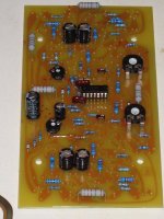
The new driver board is shaping up. As I loaded the resistors I compared them to the ones in the old board. A large percent of the old R's had values measuring 20% or higher than the indicated resistance on their color bands. They are supposed to be 5% to 10% tolerance. So in this case, it is not just the caps drying up affecting the sound, the entire amp must have been drifting?
I'm certain the sound quality will be night and day from the before and after when I'm through. All of the new R's with the exception of two will be 1% (not including the output emitter R's, they'll stay at 5%).
It's been a long night. Should be lots tomorrow and in to the weekend.
Shawn.
Attachments
How long did it take you to get your back unclenched and your eyes uncrossed after drilling that board? I always hated drilling my homemade boards - almost as much as dealing with the ferric chloride. I finally ended up putting a Dremel drill press at eye level on a couple of boxes, and I was able to drill boards without looking like the hunchback of Notre Dame afterwards.
The end result in your case is looking pretty professional, though I would maybehave chosen something besides the Piher-style pots for adjustment. Maybe that's just snobbishness on my part - the ones you chose will last a lot longer than the open-style crud you see on a lot of commercial boards.
The end result in your case is looking pretty professional, though I would maybehave chosen something besides the Piher-style pots for adjustment. Maybe that's just snobbishness on my part - the ones you chose will last a lot longer than the open-style crud you see on a lot of commercial boards.
Current address
I drilled it out in an hour. I was comfortable, the press was clamped to a countertop, I used fluorescent back light over my shoulder from behind and took a couple of deep breathes occasionally. It went well but for similar reasons to yours, I think I was avoiding the drill for a couple of days. 😉
I personally think the boards I am making are crude but I also think of most of my projects as prototypes on my first approach and that if the end result is good enough, and then I will later revisit with higher standards and more money. I’m glad you think they look pro and I guess if you compare them to the original then they are.
The pots I used were drop in replacements for the originals but something went wrong on one pair and two of the four showed up smaller than what I wanted. My final goal is to restore the amp and try hard to keep the original PCB layout. If there is a next time around I’ll certainly cut a new layout in a CAD program and optimize the set up. Change the OpAmp & the output board too. I don’t know if that is ever going to happen? It would be a lot of fun but for what?
In the end, I think I should be able to get it all done for under $100 Canadian and if I purchase the new decals and id labels it may go up to $200. If it runs as well as I think it could, at that point I’ll decide if it is worth spending the extra cash on the labels and decals. I’m optimistic and I am anticipating that it will be a full deluxe restoration, right down to the stickers and date codes that were inside the chassis. Doesn’t that sound like fun? I’m having a lot of fun with this anchor. 🙂
Cheers,
Shawn.
wrenchone said:How long did it take you to get your back unclenched and your eyes uncrossed after drilling that board? I always hated drilling my homemade boards - almost as much as dealing with the ferric chloride. I finally ended up putting a Dremel drill press at eye level on a couple of boxes, and I was able to drill boards without looking like the hunchback of Notre Dame afterwards. The end result in your case is looking pretty professional…
I drilled it out in an hour. I was comfortable, the press was clamped to a countertop, I used fluorescent back light over my shoulder from behind and took a couple of deep breathes occasionally. It went well but for similar reasons to yours, I think I was avoiding the drill for a couple of days. 😉
I personally think the boards I am making are crude but I also think of most of my projects as prototypes on my first approach and that if the end result is good enough, and then I will later revisit with higher standards and more money. I’m glad you think they look pro and I guess if you compare them to the original then they are.
... I would maybe have chosen something besides the Piher-style pots for adjustment. Maybe that's just snobbishness on my part - the ones you chose will last a lot longer than the open-style crud you see on a lot of commercial boards. [/B]
The pots I used were drop in replacements for the originals but something went wrong on one pair and two of the four showed up smaller than what I wanted. My final goal is to restore the amp and try hard to keep the original PCB layout. If there is a next time around I’ll certainly cut a new layout in a CAD program and optimize the set up. Change the OpAmp & the output board too. I don’t know if that is ever going to happen? It would be a lot of fun but for what?
In the end, I think I should be able to get it all done for under $100 Canadian and if I purchase the new decals and id labels it may go up to $200. If it runs as well as I think it could, at that point I’ll decide if it is worth spending the extra cash on the labels and decals. I’m optimistic and I am anticipating that it will be a full deluxe restoration, right down to the stickers and date codes that were inside the chassis. Doesn’t that sound like fun? I’m having a lot of fun with this anchor. 🙂
Cheers,
Shawn.
- Home
- Amplifiers
- Solid State
- Resurrecting a Crown DC300A