I am researching EL34 PP amplifiers in the hopes of building one in the near future. Google throws up about 873 billion different designs though and I just want to make sure I'm not building an unproven (or even dangerously out of spec) design with brand new and very expensive components. My main amp is currently a Maggie 9303 EL84PP modified to Dave Gillespie's design and I am very fond of the sound. I need something that will fill a larger room though and I happen to already have a matched quad of EL34s. I think my preferred setup would be a dual monoblock in separate chassis from each other. Other than that I really don't care so long as it's a respected design and not overly complicated. Anybody want to point me toward something?
You can't get anything more tried and true then the Mullard 520 circuit. Dozens of brand name amplifiers used it like the Eico HF60 just to name one. It's uncomplicated and almost foolproof. Look here and scroll down to it. Probably avoid the Williamson because it requires an exceptional output transformer do to two interstage capacitors instead of one.

You can't get anything more tried and true then the Mullard 520 circuit.
Agreed! Mullard style topology is definitely idiot resistant. A reasonable alternative to Mullard style is what's found in a Dyna ST-70.
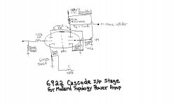
The "best" Mullard style implementation I'm aware of is the Harman-Kardon Citation V. The Cit.5 uses high transconductance (gm) small signal types to advantage. Unfortunately, the 12BY7 voltage amplifier is getting scarce. I've provided a 6922 (in production) cascode, as a 12BY7 substitute.
Attachments
This may be worth a read #322 has the schematic, its a more modern take of the 5-20 with better HF drive.
Testing newly built mullard 5-20
Testing newly built mullard 5-20
Last edited:
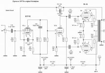
That Dynavox strongly resembles the previously mentioned Dynaco ST-70.
The 6U8/ECF82, along with the 6BL8 and 6GH8, are reasonable "replacements" for the all but unobtainable 7199.
The 6U8/ECF82, along with the 6BL8 and 6GH8, are reasonable "replacements" for the all but unobtainable 7199.
Eh, Tony, good for what? Replacing 7199s? I have some 11LQ8s that I got at $1 each and had been looking for something to do with them.
Last edited:
yes, looking at the datasheets, they are very good tubes...
you can use the triode as the input tube and the pentode wired as triode as the concertina splitter stage...
you can use the triode as the input tube and the pentode wired as triode as the concertina splitter stage...
That would be ok provided that one install SAME VALUES of theYou want simple? How about the Dynavox VR70e 🙂
Mona
cathodyn phase inverter. By some reason dynavox uses 33 and 36k here.
ECF82 is abundant and resonable priced tube that is easu to source.
Yes, you are right.I suppose it's a typo.That would be ok provided that one install SAME VALUES of the
cathodyn phase inverter. By some reason dynavox uses 33 and 36k here.
2x33k or 2x36k are both possible, doesn't make much difference.
Mona
No it's not a typo, the amps has these values. They are replaceable however.Yes, you are right.I suppose it's a typo.
2x33k or 2x36k are both possible, doesn't make much difference.
Mona
No it's not a typo, the amps has these values. They are replaceable however.

Mona
Perhaps during the early engineering phase of the original amplifier, a cathode coupled LTP was considered instead of the concertina.
Using a resistor in the coupled cathodes (and no negative voltage to that resistor) instead of a real current source would have to have the plate resistors be something like 33k and 36k, to make up for the intrinsic balance problem of using no negative high voltage supply, and using a resistor in the LTP.
Then, when engineering changed to a concertina, they retained the original resistors, and just moved one of them to the cathode.
That will cause 2nd harmonic distortion, but most of that 2nd HD will be eliminated because of the global negative feedback.
"Global Negative Feedback Covers a Multiple of Sins" - Me
. . . Just my opinions.
Last edited:
Thanks for the recommendations. None of those schematics look like they'll be a problem. Some of the ones on google look like they were part of an early computer or something. Stuff just all over the place. This is an expensive project and I just don't want to walk into it blind and start blowing up $30 tubes and $100 transformers because of a deficient design. I make enough of my own mistakes without borrowing anyone else's.
Except that the cathodyn is inherently unbalanced due to unequal resistors ( 33k/36K)That Dynavox strongly resembles the previously mentioned Dynaco ST-70.
The 6U8/ECF82, along with the 6BL8 and 6GH8, are reasonable "replacements" for the all but unobtainable 7199.
- Home
- Amplifiers
- Tubes / Valves
- Respected EL34 PP Design that's not overly complicated?