
I'm not sure what you are getting at. The OP thanked people for their responses in post #15. Maybe he got the information he needed and doesn't feel like he needs to say anything more. Nothing to pity here, I don't think...I find it a pity .
A person asks a simple and well-written question, several very competent members answer in a simple, efficient and technical way and then... nothing.
I don't understand .
...I'm not sure what you are getting at. The OP thanked people for their responses in post #15. Maybe he got the information he needed and doesn't feel like he needs to say anything more. Nothing to pity here, I don't think...
HiThanks for the recommendations. None of those schematics look like they'll be a problem. Some of the ones on google look like they were part of an early computer or something. Stuff just all over the place. This is an expensive project and I just don't want to walk into it blind and start blowing up $30 tubes and $100 transformers because of a deficient design. I make enough of my own mistakes without borrowing anyone else's.
my suggestion is to build only the project with a test lab done as certification of the specs declared
You will save time.
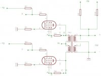
Then this is a my old project
Triode or UL with EL34
FB around 18dB
Attachments
One of my favorite Tubecad.com articles has an EL34 circuit I've breadboarded and an EL84 circuit I finished. The EL34 was very stable on the breadboard right off the bat, its something I'll come back to for sure.
https://www.tubecad.com/2010/03/blog0183.htm
https://www.tubecad.com/2010/03/blog0183.htm
EICO HF-87/89 are very straightforward to make, and the user manual shows virtually every detail of the build, not just the schematic.
https://www.vintageshifi.com/repertoire-pdf/pdf/telecharge.php?pdf=Eico-HF-89-Owners-Manual.pdf
https://www.vintageshifi.com/repertoire-pdf/pdf/telecharge.php?pdf=Eico-HF-89-Owners-Manual.pdf
Zintolo,
Another nice circuit gets posted.
Your schematic in Post # 24 does not have any DC balance adjustment for the EL34 output tubes.
1. Be sure to use very well matched EL34 pairs.
2. Or, modify the circuit for individual self bias resistors and individual bypass caps
3. Or, modify the circuit to have a DC balance control in the bias circuit; or separate individual potentiometers from the bias supply.
If you do any of the above, your output transformer will love you for the balanced plate currents.
"Prevent Early Lamination Saturation"
. . . Unless it is a Guitar amplifier, design it to saturate early, late, or at mid power level (whenever you want).
One of my favorite Tubecad.com articles has an EL34 circuit I've breadboarded and an EL84 circuit I finished. The EL34 was very stable on the breadboard right off the bat, its something I'll come back to for sure.
https://www.tubecad.com/2010/03/blog0183.htm
That PP EL34 circuit follows the general topology (shape) of the old Williamson amplifier, with four stages having multiple poles from input to output (including the OPT). Put any global NFB around it and keeping that circuit stable will get complicated, fast.
Of course if you don't put NFB around it, then it will have very high gain, and would likely be a bit noisy unless you're extremely careful with layout and power supply filtering.
I suggested a circuit like this in a previous thread, based on the 'Einstein Amplifier' from the TCJ website. It got skewered.
https://tubecad.com/2006/07/blog0073.htm
At any rate, if you're using this topology as in the two examples above without global NFB, then it should work well enough and be reasonably stable. If you're going to add NFB, the Eico HF-87 (Mullard 5-20 style) topology will be easier to deal with, because it has only one RC coupling in the signal path (the input voltage amp stage is DC coupled to the LTP, which is then AC coupled to the output stage).
rongon,
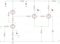
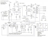
Regarding the first schematic in your Post # 30:
It seems to be either an EL34 or a 6CA7 amplifier (the only audio power output tubes I know of that have the Suppressor / Beam Formers not connected to the cathode, but instead connecting to a separate pin).
I am curious about the individual cathode circuits:
A 730 Ohm self bias resistor and bypass cap, and a specific B+ and voltage at the plate, screen, and suppressor/beam formers results in 36.5V bias.
But also, a 40V Zener is connected across them (the curious part).
It seems to me that when the average cathode current increases drastically when there are large amplitude signals, the very sharp knee'd Zener turns on Abruptly and clamps the cathode voltage to 40V, and no further.
Can you tell me, what does the Abrupt condition sound like?
Perhaps someone who has actually built this amplifier can tell us.
Just curious.
Thanks!
Last edited:
Both of those circuits were copied and pasted from John Broskie's blog.
They are PP EL34 circuits, per the thread's title, and as described in the linked blog.
The first one is from the link in Windcrest77's post (https://www.diyaudio.com/community/...ts-not-overly-complicated.358001/post-7124881)
I was pointing out the general topology, not the circuit specifics. (Williamson style vs. Mullard style.)
For specifics one would need to ask Mr. Broskie or read the blog entry. Broskie writes, "...the zeners set limits to the maximum rectification-induced increase in cathode bias voltage, as they place a 40V ceiling on the cathode resistor's bypass capacitor charging up during loud passages." It sounds to me like an attempt to mitigate blocking distortion, but I'm not 100% confident I have that correctly.
Last edited:
Are we are back to tried and true designs, versus likely untried and untrue designs?
Is there anyone out there that has built any push pull amplifier that uses individual self bias, that has this self bias network:
Self bias resistor, Bypass Cap, and a Zener that clamps increasing bias voltage?
If you can answer that, Thanks!
Is there anyone out there that has built any push pull amplifier that uses individual self bias, that has this self bias network:
Self bias resistor, Bypass Cap, and a Zener that clamps increasing bias voltage?
If you can answer that, Thanks!
I can't answer the question about the zener diodes in the cathodes, although I do think it would interfere with the class B operation area of the output pair.
But I can reply with a few tried and true PP EL34 designs.
Eli Duttman, who designed the "El Cheapo" PP 12AQ5-triode amp, expanded that to a version for PP EL34-triodes.
https://www.diyaudio.com/community/threads/why-no-simple-2-stage-el34-pp-amps.236188/#post-3496457
Allen Wright's PP-1C PP EL34 doesn't look too complicated.
http://www.vacuumstate.com/index.dna?rubrik=8&lang=2&a=%ACaJ%C4%87%7D%2B%FB&b=735374.2072390475
Member Bandersnatch posted a PP EL34 ultralinear output design with local NFB from the screen taps of the Dyna ST70 OPTs, which he called "E-Linear". Several people built that amp and reported that it sounded really nice.
https://www.diyaudio.com/community/...-push-pull-amp-need-help.131940/#post-1641087
https://www.diyaudio.com/community/attachments/6au6_st70-pdf.118435/
There is a PP EL34 version of gingertube's "Baby Huey" amplifier, which has a PCB and a build thread too.
https://www.diyaudio.com/community/threads/el34-baby-huey-amplifier.326920/
I hope that helps.
@6A3sUMMER
thanks for the suggestions, indeed you are right: I forgot to tell that I just sketched it on PSpice, so I avoided balancing systems, but I’d use a trimmer on cathodes of the phase splitter (with wiper on the CCS) and two bias circuits to better balance the output tubes as well.
Indeed for a guitar amp I’d avoid both.
My Modular amp works with EL34 and it's not overly complicated. I'm not sure how "respected" it is though.
Here's the thread. The caveat is it requires 6F12P tubes (excellent but not in production - NOS only) and there's no other tube I'm aware of with the same pinout. Good news is I have some and Ukrainian sellers are selling them again.
Of course, I wouldn't use trick OPT setup in the schematic shown for the 12AV5GA ouput for EL34, just go with Hammond or Edcor or the like. The cathode resistors are off board so you can also use the setup for cathode bias.
https://www.diyaudio.com/community/threads/modular-amplifier-1.375206/
Last edited:
My Modular amp works with EL34 and it's not overly complicated. I'm not sure how "respected" it is though.
OP, a quick sidetrack, please.
Koda,
I think your modular design could be well-respected 😁, but the trouble is that you have not provided much information in the original thread, updates, test results and PCB specifics, etc. For example, I can‘t tell what parts are on and off the PCBs. How much are the PCBs, how to get them, etc. I would like your thread revived and think it could become very popular - recent increases in “common power tubes” make the NOS sweep tubes all the more interesting.
I have update that thread - I could have sworn there was more info in that thread before.
I'll update it again shortly - I will take some better close ups of the boards etc.
I'll update it again shortly - I will take some better close ups of the boards etc.
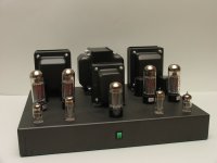
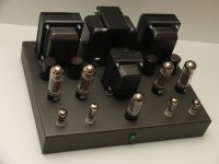
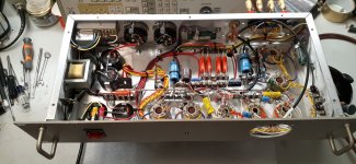
Here is an Eico HF-87 clone. Just finished building it. The chassis was an old(er) piece of telecommunication gear that I picked up somewhere (can't remember). The front panel had a meter there at one time obviuosly, but I'm going to put a piece of screen there and make it a vent for cooling.
Since trying to source an original power transformer is impossible, I used an Edcor XPWR117, which is perfect for this build. One other minor change to the original circuit was the use of a 12SL7 instead of a 12AX7. Other than that, the original circuitry was followed with minor tweaks to the feedback components to match the Edcor output transformers.
The sound quality is quite amazing. Super quiet too. Getting everything into that small chassis was a challenge, but it just required some patience and planning.
Output tubes are Svetlana EL-34's, input & driver tubes are USA NOS.
Attachments
- Home
- Amplifiers
- Tubes / Valves
- Respected EL34 PP Design that's not overly complicated?