hey, we talk about the mounting-direction of SMALLresistors on A PCB. Amp loading reistors is another thread.
But in #038 is said everything.
ingo
But in #038 is said everything.
ingo

I think those power resistors are mounted too close together to meet their datasheet thermal ratings (without forced air cooling).
If the two closely positioned resistors are not dissipating at their maximum specified ratings, then there may be no problem. If they are getting very hot, then I agree; they're too close together.
They would get quite hot if you ran a high-powered amp on this load for more than a few minutes.
Personally I would probably get some Vishay/Dale RN-series and a CPU heat sink. I have a string of RN-series on a heat sink from a cellphone base station. It works well, but I'd like to rebuild it with better connectors.
I appreciate the effort that went into measuring that the load was indeed resistive, though.
Tom
RE: Fractures at the bent lead end.
Just grip the lead with needle-nose piers between the resistor body and the bending force.
Just grip the lead with needle-nose piers between the resistor body and the bending force.
Vertical mounting of resistors are a problem if the tolerance is better than say 0.5% and no vertical spacing is added (spacer or kinked lead). When soldering, it heats the end cap on the resistor thus changing the real trimmed value. I have used glass sewing beads to resolve the problem.
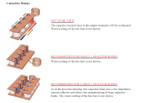
You may replace the even or odd resistors with just a return wire. https://www.celem.com/dos_and_don_tsI did that with the cheapest wirewound 10 watt cement-body resistors, to get a (mostly) noninductive composite resistor. Current flows downwards on the odd numbered resistors, and upwards on the even numbered resistors:
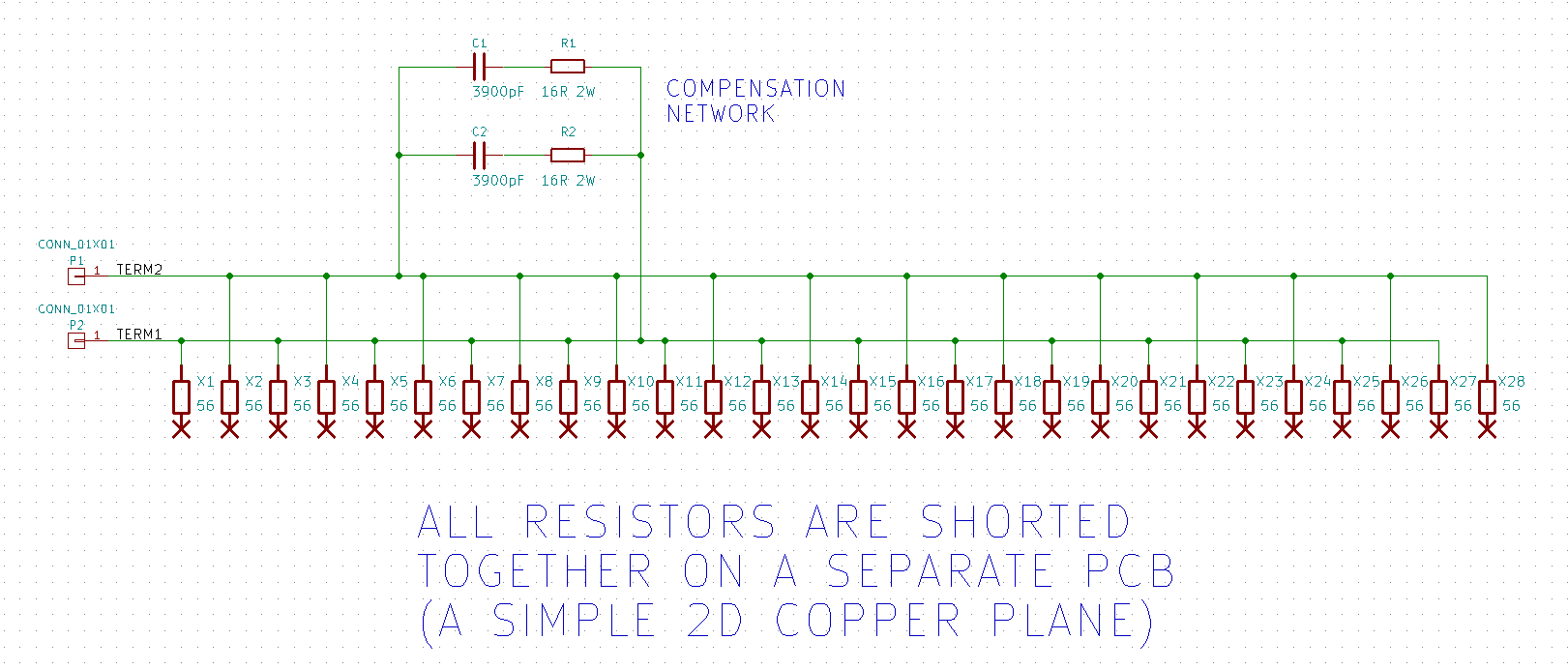
They're arranged in a two dimensional array, having four rows and seven columns. A copper plane shorts everything together on the bottom
Then, since the field cancellations were not 100.00 percent perfect, I added an RC compensator to shape the square wave response. This gave a pleasing, nearly ideal square waveform. (link)
Attachments
For those curious, position a resistor vertically and run it at half power or more. Once it gets nice and hot rapidly disconnect the power source and use a micro or milli-volt meter to measure the voltage across the hot resistor. The results depending on resistor type may surprise you. You can compare results to a horizontal unit!
Interesting question. Use an LCR meter and confirm.what about wire wound resistors?
Yep, I did. Well tried. Only have low value WW's and the LCR bottomed out at 0.6uH so inconclusive. Post #40 suggests there is something to it.Use an LCR meter and confirm
"Avoiding Passive-Component Pitfalls," Doug Grant, Scott Wurcer, Analog Dialog, 17-2, 1983.
https://proaudiodesignforum.com/forum/php/viewtopic.php?t=869
https://proaudiodesignforum.com/forum/php/viewtopic.php?t=869
Post #52 Says that Vertical mounting of resistors is wrong because they will cause thermoelectric effects. Does anyone have data on the extent of this - and can this cause a signicant error/distortion in audio ?
RE: Fractures at the bent lead end.
Just grip the lead with needle-nose piers between the resistor body and the bending force.
Or use a lead bending jig, as most of us used to do.
https://www.digikey.com/en/products...onics-ltd/TH%20LEAD%20FORMING%20TOOL/15760545
Post #52 Says that Vertical mounting of resistors is wrong because they will cause thermoelectric effects. Does anyone have data on the extent of this - and can this cause a signicant error/distortion in audio ?
It definitely exists due to the temperature differential of the two dissimilar metal junctions.
Ask Audio Precision.
Attachments
Thanks Rayma, so I guess that if it is of concern to an audio equipment manufacturer, then it must be so to audio DIYers too . . .
The impression I get from this is that although there is an effect caused by the mounting position of the resistors, it's too small to worry about from an audibility standpoint. It's like pouring a glass of water into the ocean and then expecting to see the water level rise.
my resistors all lie flat but the boards are vertical for the past number of years/decades, should I start to worry about the sound listened to and loved is now bad and could have been better all along. I always overate components by 150 - 200% because I was taught this in defence electronics the only reason for short legs and mounting close to the PCB was due to vibration. SMD components can only be mounted flat on the board. Was that also the reason that early 6 transistor radios with vertical boards with resistors mounted vertical, so that in normal orientation they are actually horizontal. 🤣 🤣 🤣 🤣 🤣 🤣There goes 50 years of my efforts right out the window. The mind boggles. Where do you guys find all this nonsense from? Even old car radios had vertical components stuffed into them to gain space and be packed denser. What about valves mounted horizontally. Does earths magnetic field bend the electron stream down?
- Home
- Source & Line
- Analog Line Level
- Resistors: horizontal or vertical?