Of course, because they are passive, if you mount them wrong way, every song will start with the end and present you some information from the devil.I’m curious, are resistors directional?
LOL, like the copper crystals in cables, eh?
Seriously, from my experience in a QA lab, any shipping will threaten tall parts, and they will fail "HALT" (Highly Accelerated Life Test), which respectable vendors require of their products. Such parts that are unavoidable will be tied down, usually with silicon. An integrated subwoofer amp has the same issue. If it's a DIY project for use in your home, then you are the warranty department and you can do or not do what you like. As others have pointed out, professionals will opt for surface mount for everything they can, for cost, mechanical and inductance issues. Handcrafting is what a hobbyist does, but professionals avoid it as much as possible.
Seriously, from my experience in a QA lab, any shipping will threaten tall parts, and they will fail "HALT" (Highly Accelerated Life Test), which respectable vendors require of their products. Such parts that are unavoidable will be tied down, usually with silicon. An integrated subwoofer amp has the same issue. If it's a DIY project for use in your home, then you are the warranty department and you can do or not do what you like. As others have pointed out, professionals will opt for surface mount for everything they can, for cost, mechanical and inductance issues. Handcrafting is what a hobbyist does, but professionals avoid it as much as possible.
what about wire wound resistors? If they have inductance and you used two in parallel, with windings in opposite directions, the inductance cancels?
Lyra had a phono preamp that used stacked boards. the Connoisseur I think.
I wondered how a couple of the circuits I was considered building might leverage that idea to make layouts more compact and elegant. These generally separated active from passive components with the power distribution comprising a third level.
I laid out a Leach phono stage and Marsh's Pooge-3 gain stage. There a mix of interconnecting resistors and wire and in the case of the Marsh a couple of constant current diodes. I wondered about loops but the moment passed and I moved on to something else.
the layouts were neat though...
Why not make a compromise and mount them in 45 degree ?
😉
😉
Never vertically. If the electrons have to travel uphill like that you can guess what happens to the sound. The large bass electrons will slow down while the treble remains the same.
Besides you don't want all the sand to leak out of the resitsor.
Besides you don't want all the sand to leak out of the resitsor.
Nope.what about wire wound resistors? If they have inductance and you used two in parallel, with windings in opposite directions, the inductance cancels?
[light bulb going on icon]Besides you don't want all the sand to leak out of the resistors.
ahhh...
I was getting tired of vacuuming up the grit every morning.
Nope. The resistor's resistance clobbers the Q of any such antenna, so any antenna effect would be picoscopic. It's a non issue. Also, at audio frequencies, there is no electromagnetic radiation of any significance to produce an effect that an antenna would be able to pick up.Thanks Eyellings,
Fortunately the unit would not be subjected to rough handling.
But the issue of loop 'antennae' effect does worry me somewhat.
Is this a significant problem in analog ?
A loop (magnetic) antenna produces a voltage due to magnetic flux passing through the loop, indepedent of any resistance. Q is irrelevant, the signal is injected as a series voltage around the loop (breaking Kirchoff's voltage law which is not a law at all of course!). The physics is very simple, the induced voltage around the loop is equal (in volts) to the rate of change of magnetic flux cutting the loop (in webers/second - Wb/s). flux is the product of magnetic flux density and area, so Wb = T.m^2.
For a sinusoidal magnetic flux density of amplitude B tesla at frequency f, the induced voltage is 2πBfA, for a loop of area A, so for instance 1 square cm will pick up ~30µV for a 1mT 50Hz alternating magnetic field that is normal to the plane of the loop.
For a sinusoidal magnetic flux density of amplitude B tesla at frequency f, the induced voltage is 2πBfA, for a loop of area A, so for instance 1 square cm will pick up ~30µV for a 1mT 50Hz alternating magnetic field that is normal to the plane of the loop.
Other factors are if the resistors have significant voltages on them, in theory a compliance tester could apply force to them to reduce clearances and cause an electrical fault or fail the compliance test. If you've got high currents flowing, you obviously want to keep the leads short to reduce ohmic losses and minimize inductance.
Calm down. We're not talking about high precision measurements or high frequency technology here. We're just talking about jelly bean 20kHz audio. And if your circuit has problems with mains hum, then the problem is definitely not with vertical resistors.
No, but if you put them in series with one rotated 180º and have 100% coupling of their magnetic fields the inductance would theoretically cancel. Getting 100% coupling is a significant challenge. One way to get there is to get "non-inductive" resistors, which are kinda constructed like that. Look up Ayrton-Perry winding: https://en.wikipedia.org/wiki/Ayrton–Perry_windingwhat about wire wound resistors? If they have inductance and you used two in parallel, with windings in opposite directions, the inductance cancels?
Tom
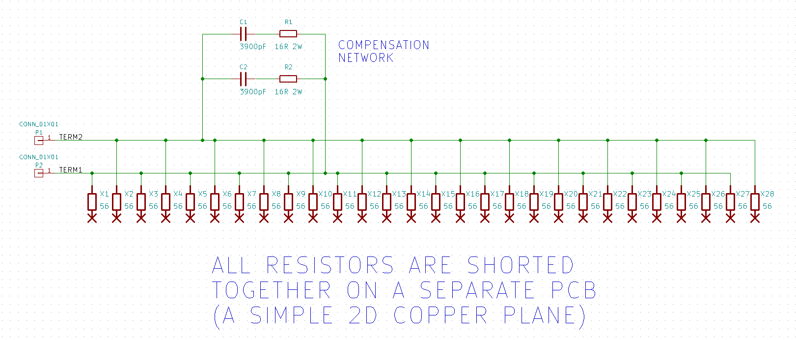
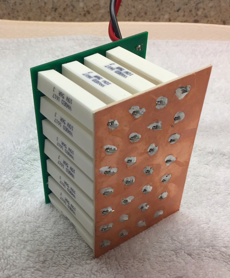
I did that with the cheapest wirewound 10 watt cement-body resistors, to get a (mostly) noninductive composite resistor. Current flows downwards on the odd numbered resistors, and upwards on the even numbered resistors:

They're arranged in a two dimensional array, having four rows and seven columns. A copper plane shorts everything together on the bottom

Then, since the field cancellations were not 100.00 percent perfect, I added an RC compensator to shape the square wave response. This gave a pleasing, nearly ideal square waveform. (link)

They're arranged in a two dimensional array, having four rows and seven columns. A copper plane shorts everything together on the bottom
Then, since the field cancellations were not 100.00 percent perfect, I added an RC compensator to shape the square wave response. This gave a pleasing, nearly ideal square waveform. (link)
- Home
- Source & Line
- Analog Line Level
- Resistors: horizontal or vertical?
