Nice looking amp. I tried to find some info for it but there ain't much.
Did you get the R value for the Vol. control while you were in there? Or at least the highest value when maxxed out to ground at the wiper? The max input impedance, in other words. If you have that then the value of the control can be found knowing the value of the other resistor in parallel.
20
Did you get the R value for the Vol. control while you were in there? Or at least the highest value when maxxed out to ground at the wiper? The max input impedance, in other words. If you have that then the value of the control can be found knowing the value of the other resistor in parallel.
20
One 300K resistor is theoretically the same as any other, any perceived differences in sound will be absolutely minor, certainly not major. I'm not saying that you wont hear a difference but the difference will be small.
There is hardly any info to be found, but its a really nice p2p wired little amp. Fun to mod aswell. Gonna measure the volume pot coz it kinda looks cheap, and i wanna replace it with a proper quality pot. Allready redid all the stock wiring and replaced the caps and resistors. Put in some NOS RCA 5693 pre amp tubes, the red metal cans which sound really nice.
The amp can take KT88, 6L6, 6550 and EL34. Tried some different tubes but the stock KT-88 sound really nice.
The amp can take KT88, 6L6, 6550 and EL34. Tried some different tubes but the stock KT-88 sound really nice.
Put the stock value of 390k in. The resistors I use are Nos Allen Bradley's and they sound great. It sounds great at stock value aswell. Might just be that the Allen Bradleys sound ghat much better than the stock chinese ones
for sure , these chinese are MOX with a lot of excess noise 🙄the Allen Bradleys sound much better than the stock chinese ones
Last edited:
Sorry, but the amp is dead silent, no noise. These are the JAN version and they are great. I know people will debate but i dont care ;-)
There is something seriously wrong if there is a massive difference between resistors of the same value.
There is something seriously wrong if there is a massive difference between resistors of the same value.
Its in details. They sound smoother, more detailed. Might be the difference in value between new and old. Sometimes tighter measured specs dont result in more pleasing sound to listen to.
Tubes are the same, transistors are measurably better in any way, but that doesnt mean they sound as good 🙂
Sorry, but the amp is dead silent, no noise. These are the JAN version and they are great. I know people will debate but i dont care ;-)
always, without any modulation , both are almost silent.
...
I noticed that on the pre amp tubes (6J8P) there is a 390k resistor to ground on the same pin where the audio signal is connected from the volume knob.
I played around a bit with different values and when i went to 600k the sound really opened up. Does anyone know what kinda value is normal in this spot?
Did you measure the old resistor to be 390K or is that how it was labeled?
Just curious based on the discussions going on. If the old one was a carbon composition type labeled to be 390K it could be significantly out of spec depending on age / environment.
The color code said 390k, i measure it at 392k
Interesting, the mystery continues. 😀
Well enough soldering for today. Time to enjoy the amp so I just put on Hugh Laurie "Didnt it rain" on vinyl and enjoying the music 🙂 must say, it sounds awesome with all the mods so far. Voices are beautiful and clear, the piano very lifelike.
Well enough soldering for today. Time to enjoy the amp so I just put on Hugh Laurie "Didnt it rain" on vinyl and enjoying the music 🙂 must say, it sounds awesome with all the mods so far. Voices are beautiful and clear, the piano very lifelike.
I really miss Harry Enfield and Chums... BBC America.
20
LOL,
Its interesting when even the manufacturers get it wrong as well..😀
But then again I buy audio parts because I can..🙂
http://www.vishaypg.com/docs/63517/FACTS-121.pdf
Regards
M. Gregg
Its interesting when even the manufacturers get it wrong as well..😀
But then again I buy audio parts because I can..🙂
http://www.vishaypg.com/docs/63517/FACTS-121.pdf
Regards
M. Gregg
Attached are the distortion curves form a carbon film resistor that is one of the worst of it's type and the same curves for a carbon composition resistor that is one of the best of it's type. Note that if you use two resistors in series the distortion will drop by 6 db. Also if you double the resistance you will get 6 db less distortion also.
So by changing the resistor from 390 K to 600K the distortion may drop 10 db. Going to a better quality one can add another 10 db. So hearing a 20 db drop in distortion is possible.
So by changing the resistor from 390 K to 600K the distortion may drop 10 db. Going to a better quality one can add another 10 db. So hearing a 20 db drop in distortion is possible.
Attachments
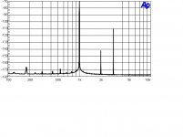
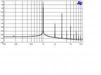
You don't label which is which, nor the test conditions or values. Meaningless, as usual.
Very sloppy work for one so (self) exalted.
Very sloppy work for one so (self) exalted.
You don't label which is which, nor the test conditions or values.
That would be too much to expect. But you can think about what the source impedance is, what the grid leak's value is, how the voltage divider looks, and the effects of the carbon comp resistor's voltage coefficient, then estimate its effect without having to worry about superficial graphs. Five minutes and a pencil.
- Status
- Not open for further replies.
- Home
- Amplifiers
- Tubes / Valves
- Resistor question