Thanks Scott.
Which?
This would do it, I think. I'm sure B&H has it a little cheaper.
https://www.amazon.com/Behringer-SRC2496-BEHRINGER-ULTRAMATCH-PRO/dp/B0002E50J0
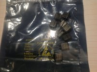
Recently i finish modify my triode preamp signal path.
All resistors now is Ayrton Perry wire wound version non-magnetic , was metal film type before.
I was sceptical is worth the efforts but after read of many articles wire wounds was more affordable option for me in this case.
Characteristics on the paper are not so far from metal bulk foils.
Wire wound can sound better if compare to metal film technology is my humble conclusion.
Less distortion on symphonic orchestral fortissimo practicaly 🙂
Attachments

Sorry I wasn't clear enough. What does the letter SRC stand for, i.e.; the initialism.
Then what does an SRC do. Thanks.
Then what does an SRC do. Thanks.
Sorry I wasn't clear enough. What does the letter SRC stand for, i.e.; the initialism.
Then what does an SRC do. Thanks.
Sample Rate Converter i.e. Takes, for instance audio at 44.1Khz and converts it to 96KHz. Please check out SRC Comparisons first, the threads here can be the typical minefield of knowledge interspersed with ignorance.
Ah I've missed you Scott! Welcome back 🙂
7 countries in 3 weeks not a day of rain.
Texas Components Corporation
video's now on line i was lucky first visitor at channel :
https://www.youtube.com/user/TexasComponentsCorp
Best regards
video's now on line i was lucky first visitor at channel :
https://www.youtube.com/user/TexasComponentsCorp
Best regards
Attachments
Resistors do distort. It is because of the temperaturecoefficient of the resistance. When a current flows thru a resistor it dissipates power and it turn will heat up the resistor. In turn the will change the value of the resistor. Low TC will help prevent that. Small resistors (SMD) will heat up faster, because of their low heat capacity.
Interesting articles. I forgot about the popcorn noise.
Interesting articles. I forgot about the popcorn noise.
Last edited:
.jpg")
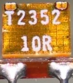
Metal Plate Cement Resistor (MPC).
The construction of these resistors is a metal plate with several cut lines to increase effective conductor length with perfectly reliable spot welded lead outs and encased in ceramic body.
Economical, easily available and probably better than WW THD/TC and non magnetic.
Also available in Dual 3 pin version, as used in billions of amplifiers.
Dan.
View attachment 603022
Metal Plate Cement Resistor (MPC).
The construction of these resistors is a metal plate with several cut lines to increase effective conductor length with perfectly reliable spot welded lead outs and encased in ceramic body.
Economical, easily available and probably better than WW THD/TC and non magnetic.
Also available in Dual 3 pin version, as used in billions of amplifiers.
Dan.
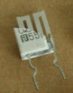
Hello Max
Yes interesting candidate for source resistors.
MPC74 Futaba 5 watts type is my favorite.

Attachments
I misspoke - when averaging FFTs, the noise floor drops by 3dB times the log base two of the number of averages, and not 3dB times the number of averages. So, if you average 8 FFTs, you get 3dB * log2(8) = 3dB * 3 = 9dB less noise. Average 64 FFTs and you get 18dB less noise.
Sorry to be sloppy, but I hope that you'll see this correction.
No you only improve the variance not the mean, gee this stuff gets everywhere. You can average 10**9 FFT's of 1nV/rt-Hz noise and get a flat line at -180dBV but no lower.
Maybe an analogy.
Suppose you role a die - the outcome will be some number between 1 and 6. Now do that 1 million times, and plot the value you got (vertical) against the roll # (horizontal). You will see a sequence of sample values between 1 and 6, 1 million times, but the average value over the whole series will be 3.5.
This is analog to your noise values that have some peak-to-peak value but a specific average value.
Now do this whole process a 1000 times, and average all the sample values with the same sample #, 1 to 1 million. For sample # 1, average them all, then for samples # 2, etc, to all 1 million sample #'s.
What you will find is that all averaged sample values of the same # will be very, very close to 3.5.
Again plot them as before. You will again get a series of values that have the average of 3.5 as before.
So the 1000 averages of the series didn't make the average lower, it is still 3.5, only it did make the peak-to-peak values come close to 3.5 as well. It almost looks like DC now ;-)
Easy, no?
Jan
Maybe an analogy.
It almost looks like DC now ;-)
Easy, no?
Jan
Yes that was my intent with the thought experiment of rolling one die, then two, then three...
Yes that was my intent with the thought experiment of rolling one die, then two, then three...
I'm a bit more long-winded, apologies ... 🙂
Jan
I'm a bit more long-winded, apologies ... 🙂
Jan
No, give yourself credit you thought it through and saw the answer. If you roll 1000 dice and add up the dots and divide by 1000 you have a hard time getting far away from 3.5.
No you only improve the variance not the mean, gee this stuff gets everywhere. You can average 10**9 FFT's of 1nV/rt-Hz noise and get a flat line at -180dBV but no lower.
Agreed, but isn't the expected value of a random process such as the 1nV/root Hz noise zero? So, yes... the variance drops, but the mu was always zero, so we just get closer to it with averaging.
Yes, not all random processes have expected values of zero, but won't Johnson noise behave like this?
The usual display is magnitude of the FFT which gives power. Any tone not exactly locked to the sampling frequency would rotate in phase and not sum as desired. So again synchronous averaging would be necessary to make this work.
Last edited:
I learned something - thanks! As it turns out, the Audio Precision uses power averaging, but if you use a waveform file and the DAC as a generator, it can do synchronous averaging in the amplitude domain. If the system were able to trigger on the generator directly, this could allow synchronous averaging using the 'nice' generator, and not just the DAC.
Still, power averaging using a wide FFT does "peel away" a lot of noise in the sense that by reducing the variance as well as the bin frequency width, actual spurs can be identified reliably in the noise floor. The "decay to a constant" property of power averaging does make sense now - thanks!
Still, power averaging using a wide FFT does "peel away" a lot of noise in the sense that by reducing the variance as well as the bin frequency width, actual spurs can be identified reliably in the noise floor. The "decay to a constant" property of power averaging does make sense now - thanks!
I learned something - thanks! As it turns out, the Audio Precision uses power averaging, but if you use a waveform file and the DAC as a generator, it can do synchronous averaging in the amplitude domain. If the system were able to trigger on the generator directly, this could allow synchronous averaging using the 'nice' generator, and not just the DAC.
You need to be careful to use the same clock, I've been burnt on this by using a USB DAC and an external digital recorder. The 96kHz sampling has to be EXACTLY the same on both devices. I would use something like ARTA to make the data and process it in PYTHON which has the MIT FFTW library built in, wicked fast and totally flexible.
- Home
- Design & Build
- Parts
- Resistor Distortion Measurement