
The first image is my motor, bolted to an acrylic prototype of the mounting bracket I've devised.
(The final bracket will be aluminum or stainless, at a thickness of 6.35 mm.)
Second is an exploded view from Technics' website, which gives you a better idea of the "pancake" design: Machined bearing housing bolted to a metal plate, that in turn is bolted to a thick PCB with the stator coils mounted on one side and (hard to see) a ring with two interlocking "tooth" shaped traces. (I assume one connects to the hall sensor and the other an error correction loop/return). The black donut is the magnet, which is epoxied to the metal bracket on top. On the SL-1200 GR2/Mk7/1500c/100c, that magnet assembly is permanently coupled to the platter, which rides on the brass outer sleeve of the spindle. Overcoming the magnetic field to lift the platter off the spindle is satisfyingly difficult.
Third is an image of the motor from an SL-1200G. Note the magnet on top, which is integral to the motor unit on the G models (the platter bolts down, rather than simply being held captive by the magnetic field. Also note that the bearing housing is more robust — and has a second magnet assembly on the bottom side of the stator PCB. Two magnets, 2x field strength (and presumably 2x torque?) As I understand it, the SP-10R motor not only has two sets of magnets, it also has two sets of stator coils (and presumably 2x data into the PLL circuit/2x resolution for error correction).
Agreed – and honestly, building something better around these specific parts is the exercise.
Incidentally, that photo of the G motor is from Devon Turnbull's instagram. Devon is the only other person I know of who is "replinthing" new generation Technics decks; this instagram post is what planted the idea for this project in my head. For those unfamiliar, Devon is behind OJAS, a boutique brand that lives between DIY, custom system builds, and the art/fashion world. In a youtube interview with Steve Guttenberg, he said that after building Garrard/Thorens plinths for several years he got interested in the G-series motors because they match the idlers in torque and beat them up in W/F and rumble. He also said that having grown up on DJ culture in 80s/90s NYC, he was intrigued by the idea of bringing the DJ gold-standard into the DIY world.
I think that's inspiring, but before I brand myself a total fanboy I'll note that Devon's decks use new OEM parts (and run $8-9k I think, BYO arm & cartridge). For my part, it's more inspiring to see people in this forum making endgame TT's from old broadcast decks that might otherwise be landfill.
I definitely want to do an SP-10 some day, and though I always look...I think I missed the window to pick one up at a flea market for a song. These parts, on the other hand, were cheap. And from an objectively high-performance turntable. I'm excited to see what they're capable of.
Can you photo your actual 100c bearing when you have a moment please ?
BTW many thanks for the steer to https://side-gallery.com/devon_turnbull_ojas_phonograph_player_system_2022/
Anyone know what he did with the 1200G controller ? BTW I reversed engineered the SP-10R CANBus control (yes really!).
BTW many thanks for the steer to https://side-gallery.com/devon_turnbull_ojas_phonograph_player_system_2022/
Anyone know what he did with the 1200G controller ? BTW I reversed engineered the SP-10R CANBus control (yes really!).
Here's bottom-view of the housing. I have this photo handy, took it while taking measurements for the bracket that couples it to my plinth. But
without a compelling reason to get inside, I'm reticent to risk cross threading it. From the exploded view in post #63 it appears there's just a disk-shaped thrust pad under that circular cap, and I can't imagine the end of the spindle is much different than previous 1200/1210 iterations

My pleasure to introduce you to Devon's work. I've heard two of his systems; one entirely of his own making/modding and the other was a pair of speakers with purpose-built active crossover/class D power amps (driven by a Kuzma table and Accuphase preamp.) Both were built around TAD drivers and both sounded fantastic.
I can't say for sure where Devon locates his motor controller, but there are clues in his photos that lead me to suspect it's somewhere in his plinth. Obviously moving the power supply outboard is advantageous. And I can tell you that the button panel PCB location is basically an aesthetic choice (it only has DC on it, and if you can live without the LEDs you can get away with just 5 wires I/O - see post #29). But in my own experiments I concluded that there's really no upside to placing the main PCB further from the motor than Technics designed it to be.
without a compelling reason to get inside, I'm reticent to risk cross threading it. From the exploded view in post #63 it appears there's just a disk-shaped thrust pad under that circular cap, and I can't imagine the end of the spindle is much different than previous 1200/1210 iterations
My pleasure to introduce you to Devon's work. I've heard two of his systems; one entirely of his own making/modding and the other was a pair of speakers with purpose-built active crossover/class D power amps (driven by a Kuzma table and Accuphase preamp.) Both were built around TAD drivers and both sounded fantastic.
I can't say for sure where Devon locates his motor controller, but there are clues in his photos that lead me to suspect it's somewhere in his plinth. Obviously moving the power supply outboard is advantageous. And I can tell you that the button panel PCB location is basically an aesthetic choice (it only has DC on it, and if you can live without the LEDs you can get away with just 5 wires I/O - see post #29). But in my own experiments I concluded that there's really no upside to placing the main PCB further from the motor than Technics designed it to be.
He might have put a linear PSU and the switches into the external box ?? Like the 10R ?there's really no upside to placing the main PCB further from the motor than Technics designed it to be.
I'm almost certain that's what he did. On the image carousel in his instagram post there's a closeup shot of his power supply board. I assume the white I/Os (lower right) run to the switches on the front panel of the PSU box, while the longer one (top left) says "to umbilical." Devon's umbilical seems to have both the +24/0v main and the and all the button trigger and LED voltages, so it follows that his main is onboard, with the motor.

Below are the guts of my 100c on the bench while I was experimenting with replacing the tact switches on the stock button-panel PCB with momentary toggles. This works great; so my plan is to locate those toggles with just the lever tips protruding from a panel, flush to the top of my plinth. (Both main and button-panel PCBs will be mounted on standoffs in a shielded pocket on the underside.)

If I get ambitious, I'll figure out which-is-which among the 11 wires connecting those boards and simply wire the main panel I/O directly to the toggles. If I get VERY ambitious I suppose could wire the main I/O to a little prototyping board and create two sets of control wires - one to the toggles, another down the umbilical to the PSU box. Voila, redundant buttons just like the 10R. (Major DIY style points...very little utility imo 🤔)
Below are the guts of my 100c on the bench while I was experimenting with replacing the tact switches on the stock button-panel PCB with momentary toggles. This works great; so my plan is to locate those toggles with just the lever tips protruding from a panel, flush to the top of my plinth. (Both main and button-panel PCBs will be mounted on standoffs in a shielded pocket on the underside.)
If I get ambitious, I'll figure out which-is-which among the 11 wires connecting those boards and simply wire the main panel I/O directly to the toggles. If I get VERY ambitious I suppose could wire the main I/O to a little prototyping board and create two sets of control wires - one to the toggles, another down the umbilical to the PSU box. Voila, redundant buttons just like the 10R. (Major DIY style points...very little utility imo 🤔)
Full disclosure, I did briefly consider offboarding all the electronics...and this isn't strictly true. It would give you ease-of-serviceability while adding mass back to the plinth. It would simplify the woodwork, too. The tradeoff is an 11-pin umbilical (double that, depending on where you want the switches) that now has to carry/shield the stator voltages, Hall, PWM & clock signals, and whatever else.there's really no upside
I'm planning an umbilical with 3-pin mini XLRs: 24v, 0V, and a braid to connect chassis grounds.
Last edited:
Avoid using XLR connectors for anything other than balanced line use. There is a risk of a connector mishap destroying other equipment. I prefer using gx-12 or gx-16 connectors to avoid accidents.
So an Oscilloscope arrived on my doorstep today (not the Rigol or Keysight but a Hantek, which seems to work well for the price). To put it through its paces, I decided to take some measurements on the stock switch mode power supply board that came with the motor. I'll have this data to compare to the PSU I'm building. Since this is my first scope, I wonder if you guys wouldn't mind checking my work...

This is the 24v DC rail. DC coupled, 2ms/div, probe right on the output of the switch mode supply (with the ground alligator on the 0v return lead).
Observations: The longer period wave is about 16ms peak to peak, which I'm told works out to around 60Hz. Meanwhile you have these noisy bursts, 2ms on, 2ms off. Assumption: Switching noise, riding on ripple, riding on the 24 v rail?

Also played around with FFT. I have the cursor over the biggest spike, not quite 60kHz, which I assume is the switching frequency. Looks like about a -70dB noise floor. Wish I could compare these to scopes of stock 1200G and SP-10R PSUs. Also curious how this compares to SP-10 PSUs you guys have built.
I get that the main PCB/Motor operates happily using this SMPS, but I have to think building a PSU that beats 40mV of ripple/switching hash and has a noise floor lower than ~70dB has to be a good thing, right?
This is the 24v DC rail. DC coupled, 2ms/div, probe right on the output of the switch mode supply (with the ground alligator on the 0v return lead).
Observations: The longer period wave is about 16ms peak to peak, which I'm told works out to around 60Hz. Meanwhile you have these noisy bursts, 2ms on, 2ms off. Assumption: Switching noise, riding on ripple, riding on the 24 v rail?
Also played around with FFT. I have the cursor over the biggest spike, not quite 60kHz, which I assume is the switching frequency. Looks like about a -70dB noise floor. Wish I could compare these to scopes of stock 1200G and SP-10R PSUs. Also curious how this compares to SP-10 PSUs you guys have built.
I get that the main PCB/Motor operates happily using this SMPS, but I have to think building a PSU that beats 40mV of ripple/switching hash and has a noise floor lower than ~70dB has to be a good thing, right?
I don't really know the Oscope well enough to measure regulation over time with it yet, but I did measure using my multimeter (ground clipped to the lug that's meant to ground the SMPS to the stock chassis, with the positive probe on the 24v rail at the output.) The results were, at least for me, pretty unexpected:
In standby mode: 33.4v DC on the output
Power on, Idling: 28.3v
Motor start: DC spikes to 28.7v
Motor run: DC settles to ~28.5v
So, most surprising is 33.4v sitting on the PSU output with everything turned off. Maybe I'm naive about how SMPSU's work, but I was expecting 0v on the 24v rail and ground return, and maybe 3.3 or 5v on the third wire btw PSU and Main, which I assume is there to power the standby mode . Also, I expected to see voltage sag during startup, but instead it spiked by only about 4mV. SO....Technics seems to have designed the PSU to overregulate, and the nominal voltage is 4.5v higher than what's specified in the service manual. So will a perfectly-regulated 24v Linear PSU be better? Or does Technics deliver that extra voltage to give headroom to some regulator or other on the Main PCB?
BTW, speaking of perfect regulation: About that startup current:
I inserted the multimeter in series with the "+24v" rail, then slow-mo videoed the screen as the current changed. The spikes were all <1s, except the braking spike from 78 rpm (about a full second):
With linear 24v dc and a 4700uF cap on the output, I feel like my PSU design can handle this. Let me know if you agree.
Also, about the current draw in 78 rpm mode:
The stock button panel PCB is clearly just a breakout board - originally it had 4 tact switches (which I replaced with momentary toggles), as well as two surface mount LEDs, and a couple resistors in series with them (also surface mount). One LED indicates 33, the other 45, and both illuminate to indicate 78. In my current design, these LEDs won't be visible from the top of the plinth, so my thought was to wire up a couple of my own in parallel, and run those to the switch panel so I'll have a visual speed indicator.

To test this, I simply dropped the leads of a spare LED into two vias on the PCB (parallel across the surface mount LEDs (and their attendant resistors). This works - BUT... when idling at 33 rpm, the current draw jumped from 37mA up to 50mA. Which is exactly what it draws in 78 rpm mode, with both the stock LEDs illuminated. So that's telling me that A LOT of the overall current drawn by this circuit is due to those LEDs. Which has me thinking more seriously about wiring the switches directly from the Main PCB I/O and eliminating that board altogether. (And if I still want LED indicators, maybe I can find some lower-current ones). Lemme know what you all think.
In standby mode: 33.4v DC on the output
Power on, Idling: 28.3v
Motor start: DC spikes to 28.7v
Motor run: DC settles to ~28.5v
So, most surprising is 33.4v sitting on the PSU output with everything turned off. Maybe I'm naive about how SMPSU's work, but I was expecting 0v on the 24v rail and ground return, and maybe 3.3 or 5v on the third wire btw PSU and Main, which I assume is there to power the standby mode . Also, I expected to see voltage sag during startup, but instead it spiked by only about 4mV. SO....Technics seems to have designed the PSU to overregulate, and the nominal voltage is 4.5v higher than what's specified in the service manual. So will a perfectly-regulated 24v Linear PSU be better? Or does Technics deliver that extra voltage to give headroom to some regulator or other on the Main PCB?
BTW, speaking of perfect regulation: About that startup current:
I inserted the multimeter in series with the "+24v" rail, then slow-mo videoed the screen as the current changed. The spikes were all <1s, except the braking spike from 78 rpm (about a full second):
| Idle | Mtr Startup | Mtr Run | Braking | |
| 33.3 | 37mA | ~625mA | 86mA | ~335mA |
| 45 | 37mA | ~625mA | 86mA | ~390mA |
| 78 | 50mA | ~690mA | 100mA | ~390mA |
With linear 24v dc and a 4700uF cap on the output, I feel like my PSU design can handle this. Let me know if you agree.
Also, about the current draw in 78 rpm mode:
The stock button panel PCB is clearly just a breakout board - originally it had 4 tact switches (which I replaced with momentary toggles), as well as two surface mount LEDs, and a couple resistors in series with them (also surface mount). One LED indicates 33, the other 45, and both illuminate to indicate 78. In my current design, these LEDs won't be visible from the top of the plinth, so my thought was to wire up a couple of my own in parallel, and run those to the switch panel so I'll have a visual speed indicator.
To test this, I simply dropped the leads of a spare LED into two vias on the PCB (parallel across the surface mount LEDs (and their attendant resistors). This works - BUT... when idling at 33 rpm, the current draw jumped from 37mA up to 50mA. Which is exactly what it draws in 78 rpm mode, with both the stock LEDs illuminated. So that's telling me that A LOT of the overall current drawn by this circuit is due to those LEDs. Which has me thinking more seriously about wiring the switches directly from the Main PCB I/O and eliminating that board altogether. (And if I still want LED indicators, maybe I can find some lower-current ones). Lemme know what you all think.
I would not worry about the LED's. I dubt they are taking anywhere near 50mA. I'm not confident on the 33.4 volt either ?
To look at start up, I monitor the voltage on the scope DC 5V per division and set the time base to about 500ms (or faster) per division so effectively 5 seconds sweep or so in total. Set to single triggered sweep and look to see if there are any issues with the output voltage dipping or something. Other settings might be better, I'm writing this from memory.
Maybe look at the input to the regulator at the same time ? Maybe trigger on input 3 (but not show it) from the motor section ? I can't remember.
All my PSU's will give way more curent than ever needed so it's never an issue.
Thanks for the info, @Dave Cawley. Here's what I found scoping the 24v output and upstream in the switching section today:
First: I ditched the JST connector on this board and soldered short jumpers in its place, in order to insert a barrier strip between the power supply and motor control PCBs. This facilitated the use a ground spring on the probe. Also, for whatever reason, the DMM now shows a rock-solid 24.18v DC on the output at all times (and yes...if it's plugged in to mains, it's powered up).
Startup regulation (DC coupled, 5v/div, 200ms sweep): I didn't get a screenshot, but the result was a flat line on the scope – and it stayed flat during startup, regardless of RPM setting. I even lifted the probe mid-sweep a few times, just to confirm the scope was working (it was; and the voltage instantly dropped to zero). So the 100/1500/Mk7 motor can draw over 650mA and the PSU doesn't blink. Out of curiosity, what's the SP-10 draw at startup?
Ripple/transients/noise (AC coupled, 100mV/div, 200ms): With no visible sag at 5v/div, I zoomed in to mV territory. (For whatever reason, the Hantek's vertical scale is limited in DC coupling mode, so this had to be done AC coupled.) Here you can clearly see ~100mV ripple/junk riding the 24v rail (at idle, under load) and while there's no visible sag, at this level you CAN see where I hit start/stop – because after the initial 300mV transient, the ripple actually decreases for the duration of the current spike. Definitely not what I expected... so if anyone can explain, I'm interested.

Regulator input (DC coupled, 50v/div, 2ms) Probed what I think is the regulator input (Seems the 40-year old Technics service manuals have full schematics...the new ones don't). This trace looked crazy until I zoomed out/sped up enough to grab the entire 120v pk-pk waveform. I suspect those are the same ~2ms fuzzy transients I showed in post #74. This waveform got "fuzzier" during motor start, but the overall shape/amplitude remained constant.

Next steps: So... the stock power supply's voltage regulation might be hard to beat. But the 100mV of ripple and switching noise seem...high. Parts for my linear supply are starting to arrive in the mail, so hopefully by next week I can get it on a breadboard and post some comparisons. Thanks again for all your help and interest!
First: I ditched the JST connector on this board and soldered short jumpers in its place, in order to insert a barrier strip between the power supply and motor control PCBs. This facilitated the use a ground spring on the probe. Also, for whatever reason, the DMM now shows a rock-solid 24.18v DC on the output at all times (and yes...if it's plugged in to mains, it's powered up).
Startup regulation (DC coupled, 5v/div, 200ms sweep): I didn't get a screenshot, but the result was a flat line on the scope – and it stayed flat during startup, regardless of RPM setting. I even lifted the probe mid-sweep a few times, just to confirm the scope was working (it was; and the voltage instantly dropped to zero). So the 100/1500/Mk7 motor can draw over 650mA and the PSU doesn't blink. Out of curiosity, what's the SP-10 draw at startup?
Ripple/transients/noise (AC coupled, 100mV/div, 200ms): With no visible sag at 5v/div, I zoomed in to mV territory. (For whatever reason, the Hantek's vertical scale is limited in DC coupling mode, so this had to be done AC coupled.) Here you can clearly see ~100mV ripple/junk riding the 24v rail (at idle, under load) and while there's no visible sag, at this level you CAN see where I hit start/stop – because after the initial 300mV transient, the ripple actually decreases for the duration of the current spike. Definitely not what I expected... so if anyone can explain, I'm interested.
Regulator input (DC coupled, 50v/div, 2ms) Probed what I think is the regulator input (Seems the 40-year old Technics service manuals have full schematics...the new ones don't). This trace looked crazy until I zoomed out/sped up enough to grab the entire 120v pk-pk waveform. I suspect those are the same ~2ms fuzzy transients I showed in post #74. This waveform got "fuzzier" during motor start, but the overall shape/amplitude remained constant.
Next steps: So... the stock power supply's voltage regulation might be hard to beat. But the 100mV of ripple and switching noise seem...high. Parts for my linear supply are starting to arrive in the mail, so hopefully by next week I can get it on a breadboard and post some comparisons. Thanks again for all your help and interest!
Well done ! Some times scope probes pick up stuff that is just in the air or on a chassis and if you remove all power it may or may not still be there.
Also I forgot to mention that the SMPS does radiate "stuff" and that can and will get into the cartridge which is quite close, Bearing in mind the dynamic range/sensitivity of our ears is very high, it may or may not be perceptible as a loss of detail. It may be expectation bias and YMMV.
Also I forgot to mention that the SMPS does radiate "stuff" and that can and will get into the cartridge which is quite close, Bearing in mind the dynamic range/sensitivity of our ears is very high, it may or may not be perceptible as a loss of detail. It may be expectation bias and YMMV.
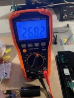
Hey, all. It's been a week and I have a working circuit, a bunch of measurements, and a new problem to solve. This may prove to be a lengthy post about what most of you consider Electronics 101, so thanks in advance to anyone who reads it thru. Since I'm still a newb who is learning by doing, advice is warmly solicited. Anyway, here's junior's first breadboard:

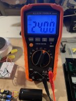
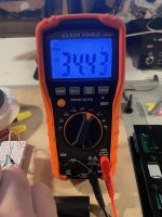
Voltages (w/ 75 ohm, 5W dummy load):
Mains secondary - 26.82
Peak DC at the filter input, after the rectifier - 34.43
Regulator input, after the filter - 33.97.
Across the output... bang-on 24v DC 🎯
(Thanks for the recommendation on that 7824 regulator, @6L6)
Inrush Stress Test (w/8 ohm, 50W dummy load):
I put the big resistor (and also CH1 of my scope) across the output, with CH2 across the regulator input. I wasn't sure how fast the resistor would get hot, I switched the PSU on for about 15 seconds, then switched it back off. The traces races leapt instantly to 24v (output) and 34v (before the regulator). Applying Ohm's law, this circuit delivered 3A across the output with no overshoot or ringing. Excellent. Next up...


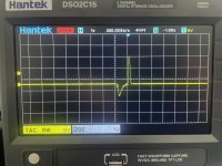
The first image above is the capture from post #78 – Motor start (to 33rpm) with the SMPS. 100mv/div, AC coupled.
The second image is a capture from earlier today – Motor start (@ 33) with the LPS. Exact same scope settings. Night and day, yes?
First of all, LPS has 20mV of noise riding the DC rail vs 100mV with the SMPS. Second: SMPS sees a 300mV transient (followed by brief relative silence) the instant the switch is thrown, while LPS sees a much longer switch transient that swings off-the-chart voltage, but manages to float back down for a soft landing. Third: on both captures, there seems to be a bit more noise on the rail once the motor settles in at 33 rpm.
Incidentally, I used RPM app to log the platter speed and W/F during these tests. Absolute speed accuracy was a dead heat between PSUs – although on multiple trials, W&F was decreased .01% with the linear supply. I'm sure most would argue a hundreth is totally inaudible, and probably within an iphone accelerometer's margin for error anyway... But whatever, the LPS gives the Main PCB a much cleaner 24v rail to work with. NEXT, let's do 45 rpm...

Here, I've zoomed out to 2v/div so we can grab the whole waveform, which is ~14v pk-pk. And because the filter's series resistance is 10 ohms, I believe (I = V/R) that means the instantaneous motor startup current spike is ~1.4 A. (Note: The scope showed the same startup voltage swing for 33 and 45, which is consistent with multimeter current readings last week, where 33 and 45 drew roughly the same current at startup.)
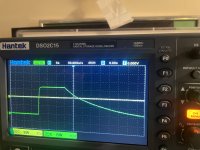
NEXT is startup for 78 rpm and... Houston, we have a problem:

Hitting start/stop with 78 selected causes a massive, noisy voltage swing followed by an immediate Main PCB shutdown. (That trail of little 200mV spikes after the startup fail are the button LEDs blinking to indicate the motor controller detected undervoltage and shut itself down.)
Now.... We know from last week's DMM readings that the motor asks for significantly more current to get up to 78 rpm.
So here's that startup event, zoomed out to 5v/div to get the whole wave:

So now we know that the swing caused by the motor as it tries to get to 78 is almost 18v pk-pk, (versus. 14v for 33/45).
V / R = I
14/10 = 1.4 A
18/10 = 1.8 A
@Dave Cawley I now fully understand why you brought up motor startup current and expressed concerns about the series resistance of the filter. I infer from those concerns – and because I have 4700uF across the output of my regulator – that the problem of Filter dropping too many volts = Insufficient headroom at the regulator = One way ticket to Dropout City.
So my question is this:
Would you reduce R values in the CRCRC filter and live with a little more ripple?
Or would you assume the .33 uF cap Onsemi recommends for the regulator input is the minimum value, and maybe use that .33 as a bypass on a MUCH bigger cap, ensuring there's always enough juice onhand to avoid a dropout?
Thanks again to any of you who will take time to respond!!

Voltages (w/ 75 ohm, 5W dummy load):
Mains secondary - 26.82
Peak DC at the filter input, after the rectifier - 34.43
Regulator input, after the filter - 33.97.
Across the output... bang-on 24v DC 🎯
(Thanks for the recommendation on that 7824 regulator, @6L6)
Inrush Stress Test (w/8 ohm, 50W dummy load):
I put the big resistor (and also CH1 of my scope) across the output, with CH2 across the regulator input. I wasn't sure how fast the resistor would get hot, I switched the PSU on for about 15 seconds, then switched it back off. The traces races leapt instantly to 24v (output) and 34v (before the regulator). Applying Ohm's law, this circuit delivered 3A across the output with no overshoot or ringing. Excellent. Next up...
The first image above is the capture from post #78 – Motor start (to 33rpm) with the SMPS. 100mv/div, AC coupled.
The second image is a capture from earlier today – Motor start (@ 33) with the LPS. Exact same scope settings. Night and day, yes?
First of all, LPS has 20mV of noise riding the DC rail vs 100mV with the SMPS. Second: SMPS sees a 300mV transient (followed by brief relative silence) the instant the switch is thrown, while LPS sees a much longer switch transient that swings off-the-chart voltage, but manages to float back down for a soft landing. Third: on both captures, there seems to be a bit more noise on the rail once the motor settles in at 33 rpm.
Incidentally, I used RPM app to log the platter speed and W/F during these tests. Absolute speed accuracy was a dead heat between PSUs – although on multiple trials, W&F was decreased .01% with the linear supply. I'm sure most would argue a hundreth is totally inaudible, and probably within an iphone accelerometer's margin for error anyway... But whatever, the LPS gives the Main PCB a much cleaner 24v rail to work with. NEXT, let's do 45 rpm...
Here, I've zoomed out to 2v/div so we can grab the whole waveform, which is ~14v pk-pk. And because the filter's series resistance is 10 ohms, I believe (I = V/R) that means the instantaneous motor startup current spike is ~1.4 A. (Note: The scope showed the same startup voltage swing for 33 and 45, which is consistent with multimeter current readings last week, where 33 and 45 drew roughly the same current at startup.)
NEXT is startup for 78 rpm and... Houston, we have a problem:
Hitting start/stop with 78 selected causes a massive, noisy voltage swing followed by an immediate Main PCB shutdown. (That trail of little 200mV spikes after the startup fail are the button LEDs blinking to indicate the motor controller detected undervoltage and shut itself down.)
Now.... We know from last week's DMM readings that the motor asks for significantly more current to get up to 78 rpm.
So here's that startup event, zoomed out to 5v/div to get the whole wave:
So now we know that the swing caused by the motor as it tries to get to 78 is almost 18v pk-pk, (versus. 14v for 33/45).
V / R = I
14/10 = 1.4 A
18/10 = 1.8 A
@Dave Cawley I now fully understand why you brought up motor startup current and expressed concerns about the series resistance of the filter. I infer from those concerns – and because I have 4700uF across the output of my regulator – that the problem of Filter dropping too many volts = Insufficient headroom at the regulator = One way ticket to Dropout City.
So my question is this:
Would you reduce R values in the CRCRC filter and live with a little more ripple?
Or would you assume the .33 uF cap Onsemi recommends for the regulator input is the minimum value, and maybe use that .33 as a bypass on a MUCH bigger cap, ensuring there's always enough juice onhand to avoid a dropout?
Thanks again to any of you who will take time to respond!!
Attachments
- Home
- Source & Line
- Analogue Source
- Rescuing & Reimagining a Technics SL-100c