
An update to bump the thread. Here's what I hope ultimately comes together.

You guys are probably growing weary of looking at my CAD drawings (I know I am).
I know, just GET TO BUILDING, man!
The capital-B Bottleneck has been learning CAD from the ground up. There's been a lot of reading and tutorial-watching and I think it's time well-spent toward both (a) ending up with something that looks worthy of my other gear; and (b) avoiding expensive mistakes. Thus every sketch, extrusion and assembly has been through a (hums Led Zeppelin to self) WHOLE LOTTA iterations.
Another update - with burning questions - is coming VERY soon!
That is great!
And I love the drawings, I can’t imagine anybody complaining.
And did I miss an explanation somewhere as to why the plinth is so incredibly large? Is it pure aesthetics or are you engineering something specific…? Don’t get me wrong, it’s really cool, but I wonder if you are going to find it challenging to deal with in handling, or material cost, or even storage and use. Just thinking out loud.
Oh, it's pure aesthetics. At least mostly.
The idea is to make the plinth work (visually) with the "rack" it will sit on... a credenza-style unit made of recycled wood. Also, my CAD drawing may be deceptive... those controls above are MUCH smaller than the stock buttons — an idea I'll seek advice on below.
Okay, don't laugh: I designed the footprint to the golden ratio. This, again, is aesthetic, and not about any sonic belief. I started with the depth of my current table—a VPI—and then let the ratio dictate the width. That gives you roughly 17 x 27". (The plinth is upside down below for comparison's sake.) Obviously, I could just lop off everything beyond the pivot-end of the tonearm hole. But then the spindle wouldn't sit at the exact midpoint of the line that joins the square of the short side to the long side of the next-smallest golden rectangle. And that would make Euclid sad.


For real-world context, here's my rack. Note the tape — that's 27". So really, this thing won't be all that much wider than the VPI. And it's roughly the same depth. And (I think) at 4" it'll look a whole lot sleeker. Not to mention....a hell of a lot more torque. 😏

All that said - there is SOME method to my madness:
One design imperative is to keep the digital/high frequency signal as far from musical signal as I can. A 700mm wide turntable certainly accommodates this, but it does run into a competing parameter, which is mass directly below the motor mount. This means the recess for the electronics in the plinth's bottom has to be outboard of the recess in the topside for the motor bracket. As you can see, this pushes the motor control PCB farily close to the left edge of the plinth:

The recess for the controller PCB is 1" deep, and since the plan is to stack four 1" plywood sheets, and the main cutout goes all the way thru. There are also two channels that go partially through that first layer: one (to be routed from the bottom) for the harness between the controller PCB and the motor's stator PCB , and the other (to be routed from the top) for the umbilical to the power supply.
Since these channels will have to be routed from opposing faces of the plinth's bottom layer, (I'm assuming) the part will have to be flipped and realigned on the machine. Anyone with CNC experience, please chime in and let me know if any of this looks wrong and/or noob-ish to you.
The bigger challenge is the additional holes/recesses that will need to be cut into layers above this recess in order to accommodate the wiring and/or additional parts for the control button panel.
I mentioned above that I have questions for the forum about the button panel and PCB, but it's getting late and I think that topic should really be its own post. Suffice it to say that devising a way to orient and mount the buttons in this plinth are so far the biggest challenge – by a long shot – and I've been through no less than 5 design iterations. I'll put a post together tomorrow or over the weekend.
Thanks to everyone/anyone reading this... and especially you, @6L6 - the encouragement means a lot!
The idea is to make the plinth work (visually) with the "rack" it will sit on... a credenza-style unit made of recycled wood. Also, my CAD drawing may be deceptive... those controls above are MUCH smaller than the stock buttons — an idea I'll seek advice on below.
Okay, don't laugh: I designed the footprint to the golden ratio. This, again, is aesthetic, and not about any sonic belief. I started with the depth of my current table—a VPI—and then let the ratio dictate the width. That gives you roughly 17 x 27". (The plinth is upside down below for comparison's sake.) Obviously, I could just lop off everything beyond the pivot-end of the tonearm hole. But then the spindle wouldn't sit at the exact midpoint of the line that joins the square of the short side to the long side of the next-smallest golden rectangle. And that would make Euclid sad.
For real-world context, here's my rack. Note the tape — that's 27". So really, this thing won't be all that much wider than the VPI. And it's roughly the same depth. And (I think) at 4" it'll look a whole lot sleeker. Not to mention....a hell of a lot more torque. 😏
All that said - there is SOME method to my madness:
One design imperative is to keep the digital/high frequency signal as far from musical signal as I can. A 700mm wide turntable certainly accommodates this, but it does run into a competing parameter, which is mass directly below the motor mount. This means the recess for the electronics in the plinth's bottom has to be outboard of the recess in the topside for the motor bracket. As you can see, this pushes the motor control PCB farily close to the left edge of the plinth:
The recess for the controller PCB is 1" deep, and since the plan is to stack four 1" plywood sheets, and the main cutout goes all the way thru. There are also two channels that go partially through that first layer: one (to be routed from the bottom) for the harness between the controller PCB and the motor's stator PCB , and the other (to be routed from the top) for the umbilical to the power supply.
Since these channels will have to be routed from opposing faces of the plinth's bottom layer, (I'm assuming) the part will have to be flipped and realigned on the machine. Anyone with CNC experience, please chime in and let me know if any of this looks wrong and/or noob-ish to you.
The bigger challenge is the additional holes/recesses that will need to be cut into layers above this recess in order to accommodate the wiring and/or additional parts for the control button panel.
I mentioned above that I have questions for the forum about the button panel and PCB, but it's getting late and I think that topic should really be its own post. Suffice it to say that devising a way to orient and mount the buttons in this plinth are so far the biggest challenge – by a long shot – and I've been through no less than 5 design iterations. I'll put a post together tomorrow or over the weekend.
Thanks to everyone/anyone reading this... and especially you, @6L6 - the encouragement means a lot!
PS - speaking of enormous plinths:
Hey, that wouldn't happen to be a Garrard 301 seamlessly integrated into the solid ash surface of one of the most gorgeous pieces of audio furniture I've ever seen?

Why, yes. Yes it would be.

Apparently, that rack also has pneumatic isolation feet.
The guy's instagram handle is @garrarddandy, check him out.
Hey, that wouldn't happen to be a Garrard 301 seamlessly integrated into the solid ash surface of one of the most gorgeous pieces of audio furniture I've ever seen?
Why, yes. Yes it would be.
Apparently, that rack also has pneumatic isolation feet.
The guy's instagram handle is @garrarddandy, check him out.
As advertised, here's more info, and a request for thoughts and expertise on....
The Control Panel Bottleneck
At some point, Technics abandoned individual (and I think, metal) buttons for a single hunk-o-plastic that integrates extruded buttons. Each is on its own flexible "leaf" that taps a TACT switch soldered to the control PCB.

In the stock 100c, that PCB is screwed directly to the aluminum top panel — the button panel is simply held captive between them. Using this part in my build would mean an awkwardly shaped, millimeter-accurate cut nearly all the way though the plinth.
This seems risky, or at least unlikely to generate a professional-looking result (the thrashed buttons don't help.) So my instinct was to design a similar part from scratch. I'd still use a “flex-leaf” button design, but the form factor will require simpler cutouts and thus be easier to mount, as well as have metal buttons and a metal panel section surrounding them. I've been through a bunch of iterations on that part, which I'll go into details in a future post if I go that route. But first...
I'm wondering if folks might take a look images from the service manual and weigh in on some questions/ideas for a different approach:
There are very few components on this PCB: 4 momentary TACT switches — Power, Start/Stop, 33 and 45; 2 speed-indicator LEDs; a few surface-mount resistors along the LED's traces. (Pressing 33 and 45 simultaneously lights both LEDs and gives you 78.) Here are some images, and my questions below:


1. There's 24v DC on Pin 2 of the board. On the block diagram, it looks like those volts are only there to power the LEDs — does anyone disagree with my interpretation of the bock diagram?
2. The TACT switches are soldered to the PCB at two points, which leads me to think they're SPST. Does anyone think there's a reason I couldn't take those switches out and solder lengths of wire in their place, thus giving myself the option to move them?
3. If the scenario in #2 is possible, is there any reason a different type of SPST momentary switch wouldn't work in this application? And couldn't I also wire up a third switch to close the 33 and 45 circuits simultaneously to create a discrete 78 switch?
4. Given the very few components on this PCB, is it safe to say whatever the logic those TACTs operate is happening on the main PCB that controls the motor? If so, I know what Pin 2 is for (and I assume Pin 1 is ground)... what would be the best way to go about discovering which-is-which for the other wires running into this board?
If I knew, I could eliminate this awkwardly-shaped PCB altogether. I saw some vintage momentary toggles/buttons at Leeds Radio and started thinking about what something like that could look like:

The Control Panel Bottleneck
At some point, Technics abandoned individual (and I think, metal) buttons for a single hunk-o-plastic that integrates extruded buttons. Each is on its own flexible "leaf" that taps a TACT switch soldered to the control PCB.
In the stock 100c, that PCB is screwed directly to the aluminum top panel — the button panel is simply held captive between them. Using this part in my build would mean an awkwardly shaped, millimeter-accurate cut nearly all the way though the plinth.
This seems risky, or at least unlikely to generate a professional-looking result (the thrashed buttons don't help.) So my instinct was to design a similar part from scratch. I'd still use a “flex-leaf” button design, but the form factor will require simpler cutouts and thus be easier to mount, as well as have metal buttons and a metal panel section surrounding them. I've been through a bunch of iterations on that part, which I'll go into details in a future post if I go that route. But first...
I'm wondering if folks might take a look images from the service manual and weigh in on some questions/ideas for a different approach:
There are very few components on this PCB: 4 momentary TACT switches — Power, Start/Stop, 33 and 45; 2 speed-indicator LEDs; a few surface-mount resistors along the LED's traces. (Pressing 33 and 45 simultaneously lights both LEDs and gives you 78.) Here are some images, and my questions below:
1. There's 24v DC on Pin 2 of the board. On the block diagram, it looks like those volts are only there to power the LEDs — does anyone disagree with my interpretation of the bock diagram?
2. The TACT switches are soldered to the PCB at two points, which leads me to think they're SPST. Does anyone think there's a reason I couldn't take those switches out and solder lengths of wire in their place, thus giving myself the option to move them?
3. If the scenario in #2 is possible, is there any reason a different type of SPST momentary switch wouldn't work in this application? And couldn't I also wire up a third switch to close the 33 and 45 circuits simultaneously to create a discrete 78 switch?
4. Given the very few components on this PCB, is it safe to say whatever the logic those TACTs operate is happening on the main PCB that controls the motor? If so, I know what Pin 2 is for (and I assume Pin 1 is ground)... what would be the best way to go about discovering which-is-which for the other wires running into this board?
If I knew, I could eliminate this awkwardly-shaped PCB altogether. I saw some vintage momentary toggles/buttons at Leeds Radio and started thinking about what something like that could look like:
Absolutely!Are you going to take advantage of this?
The armboard is going to accommodate pivot-to-spindle from 210 to 300+ mm and I want to experiment, but I'd say there's about a 99% chance the first arm I go for with this deck will be 12".
I put these points into the drawing while working on the cutout dimensions. At the moment I'm spending a fair amount of time browsing ebay for vintage Japanese arms. From shortest to longest below, I measured for:
Jelco SA-250
The JMW 10.5 3D on my current table
Micro Seiki MA-505L
STAX UA-70
Schick 12"
Ortofon, EMT, plenty of others on the table, too. So many cool arms out there, I'm open to suggestions!
Well... it's been well over a month, work and other obligations have stymied my progress, and the few folks who were following this build have likely forgotten about it, but—
Bump. Here's a detailed update.
So a couple weeks ago I spent a Saturday afternoon talking with a few experts: One does turntable setups and is very familiar with Technics gear; another is the owner of eight(!) idler-drive tables in plinths of various designs; and the third is the owner of a local hifi store and an all-around brilliant dude. This conversation resulted in some changes and simplifications to the design:


Smaller, reconfigured plinth.
The deck's depth is the same, but the the motor/platter has moved toward the center of the plinth, and the overall width has been reduced to roughly the minimum necessary to accommodate the armboard and the control PCB.
The main PCB has now rotated 90 degrees from its position in earlier versions of this design. This puts the 11-pin connector for the wiring harness as close to its counterpart on the motor's stator PCB as possible. This means the stock ribbon cable can be used in the final build. In conversation with the group, it was suggested that the length of that cable may figure into the performance of the speed sensing and correction signals. And in any case, I've had no success in finding a ribbon connector that makes a snug mechanical connection with the stock JST jacks mounted on the PCBs.
Also abandoned is the idea to recess the vertical outer edge of the platter into the top layer of the plinth. Sleek as that would look, it puts the record surface VERY close to the deck, which could limit tonearm choices and present VTA or other setup problems.
Solving the control panel. For a long time I went back-and-forth about using the stock button panel. I eventually landed on a simple way to incorporate it, but given overall condition and plasticky feel – I wanted to design something original for this project. A classic look, solid feel and a discrete switch for 78 were imperatives (the stock configuration requires you to press 33 and 45 simultaneously to get 78 which seems a bit of an afterthought.)
Here's what I came up with:

Unfortunately no one weighed in on my questions regarding the control panel PCB. And the response from the guys I talked to in person was, "Wow, good luck with that." Undaunted, I pulled out the soldering iron and rolled the dice.

Tact switches removed from the board, wires soldered in.

SPST momentary toggles. They feel wonderfully solid.
My initial hunches (Post #27) proved correct – all the logic pertaining to power and motor control happens on the main PCB. The panel PCB exists solely to mount the switches and LEDs under their respective buttons on the stock deck.
BUT... inexperienced as I am, it actually took a total dissection and P2P re-wiring for me to realize how this circuit actually works: Power, Start/Stop, 33 and 45, are straightforward – momentarily connect the "hot" lead of any switch to ground, and you'll trigger the logic flop associated with that switch. Power, Start/Stop, 33 and 45 are all a simple matter of replacing the PCB-mount tact button with the SPST momentary toggle. Also – again, total newb here – it took some experimentation to understand that a simultaneous press of 33 and 45 is simply the equivalent of connecting the "hot" leads both the 33 and 45 to ground at the same time and (again, probably obviously to most people on this forum) it doesn't matter which ground lead you choose to make that connection.
So to simulate that action using a 5th momentary toggle as a dedicated 78 switch, you need 33 and 45 to be connected when you close the circuit to trigger the flop – but they need to be UNCONNECTED when the switch returns to the "normally off" position. Otherwise, throwing ANY speed switch will give you 78, with no way back to 33 or 45.
So I ran jumpers from the 33 and 45 switches and spent an embarrassing amount of time thinking about how to wire them up a DPDT to make the 78 switch... until I stumbled onto the idea of putting a diode at the end of each jumper, just before the "hot" terminal of a SPST momentary that I already had on hand. Close that switch, suddenly both 33 & 45 can "see" ground thru the diodes. But when the switch snaps back open, the diodes prevent continuity between them, so they operate normally.

Alligator clips for the win. Obviously the final build will be way less janky.
I'm honestly not sure I could draw a schematic for this circuit on a piece of paper, but it works like a charm.
So... here's where we are: Tomorrow I'll order the last round of acrylic prototypes from Send Cut Send to make a final confirmation that everything will fit together, and I'll get on my buddy about making some time for me on his CNC to cut the plinth.
This project is a slow burn, but I think it's going to be worth it.

Bump. Here's a detailed update.
So a couple weeks ago I spent a Saturday afternoon talking with a few experts: One does turntable setups and is very familiar with Technics gear; another is the owner of eight(!) idler-drive tables in plinths of various designs; and the third is the owner of a local hifi store and an all-around brilliant dude. This conversation resulted in some changes and simplifications to the design:
Smaller, reconfigured plinth.
The deck's depth is the same, but the the motor/platter has moved toward the center of the plinth, and the overall width has been reduced to roughly the minimum necessary to accommodate the armboard and the control PCB.
The main PCB has now rotated 90 degrees from its position in earlier versions of this design. This puts the 11-pin connector for the wiring harness as close to its counterpart on the motor's stator PCB as possible. This means the stock ribbon cable can be used in the final build. In conversation with the group, it was suggested that the length of that cable may figure into the performance of the speed sensing and correction signals. And in any case, I've had no success in finding a ribbon connector that makes a snug mechanical connection with the stock JST jacks mounted on the PCBs.
Also abandoned is the idea to recess the vertical outer edge of the platter into the top layer of the plinth. Sleek as that would look, it puts the record surface VERY close to the deck, which could limit tonearm choices and present VTA or other setup problems.
Solving the control panel. For a long time I went back-and-forth about using the stock button panel. I eventually landed on a simple way to incorporate it, but given overall condition and plasticky feel – I wanted to design something original for this project. A classic look, solid feel and a discrete switch for 78 were imperatives (the stock configuration requires you to press 33 and 45 simultaneously to get 78 which seems a bit of an afterthought.)
Here's what I came up with:
Unfortunately no one weighed in on my questions regarding the control panel PCB. And the response from the guys I talked to in person was, "Wow, good luck with that." Undaunted, I pulled out the soldering iron and rolled the dice.
Tact switches removed from the board, wires soldered in.
SPST momentary toggles. They feel wonderfully solid.
My initial hunches (Post #27) proved correct – all the logic pertaining to power and motor control happens on the main PCB. The panel PCB exists solely to mount the switches and LEDs under their respective buttons on the stock deck.
BUT... inexperienced as I am, it actually took a total dissection and P2P re-wiring for me to realize how this circuit actually works: Power, Start/Stop, 33 and 45, are straightforward – momentarily connect the "hot" lead of any switch to ground, and you'll trigger the logic flop associated with that switch. Power, Start/Stop, 33 and 45 are all a simple matter of replacing the PCB-mount tact button with the SPST momentary toggle. Also – again, total newb here – it took some experimentation to understand that a simultaneous press of 33 and 45 is simply the equivalent of connecting the "hot" leads both the 33 and 45 to ground at the same time and (again, probably obviously to most people on this forum) it doesn't matter which ground lead you choose to make that connection.
So to simulate that action using a 5th momentary toggle as a dedicated 78 switch, you need 33 and 45 to be connected when you close the circuit to trigger the flop – but they need to be UNCONNECTED when the switch returns to the "normally off" position. Otherwise, throwing ANY speed switch will give you 78, with no way back to 33 or 45.
So I ran jumpers from the 33 and 45 switches and spent an embarrassing amount of time thinking about how to wire them up a DPDT to make the 78 switch... until I stumbled onto the idea of putting a diode at the end of each jumper, just before the "hot" terminal of a SPST momentary that I already had on hand. Close that switch, suddenly both 33 & 45 can "see" ground thru the diodes. But when the switch snaps back open, the diodes prevent continuity between them, so they operate normally.
Alligator clips for the win. Obviously the final build will be way less janky.
I'm honestly not sure I could draw a schematic for this circuit on a piece of paper, but it works like a charm.
So... here's where we are: Tomorrow I'll order the last round of acrylic prototypes from Send Cut Send to make a final confirmation that everything will fit together, and I'll get on my buddy about making some time for me on his CNC to cut the plinth.
This project is a slow burn, but I think it's going to be worth it.
Package arrived from Send Cut Send yesterday. In it, prototypes of all my metal part designs.
As discussed a bunch of posts ago, I had these made from acrylic, which is SCS's least expensive laser-cut material. Obvious reason: less-costly mistakes. So far, everything fits, but there are already a few instances where I'm considering shape refinements.

Also in the box were some Sour Patch Kids. You get candy with every order from Send Cut Send.
Nice touch, guys.


Motor mount. Not pictured, the three machine screws that couple it to the bearing housing from the underside. Spot on fit.
(Never posted it, but this took several acrylic models to get right.)


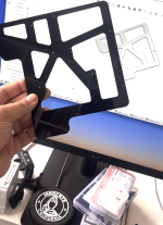
Control panel. The prototype is bolted together thru nylon spacers. The real thing will be 7075 aluminum with countersunk screw holes. I'll keep the spacers but use wood screws to go right into the plinth, likely with strip of 3M viscoelastic/aluminum tape between the bottom panel and the bare wood. Also will source nylon washers to replace the ones that came with the toggles and ditch the screw terminals for solder. Anything that might rattle has gotta go.


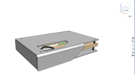
Left: Speed control chassis design. The chassis is designed to sandwich the main motor controller and button panel PCBs between upper and lower metal plates using standoffs and/or spacers between the layers. This unit will fit into a recessed area on the bottom of the plinth. You're looking at the top plate in this image, the holes are for ventilation and to route/accommodate wiring harnesses.

This is the bottom plate of the electronics chassis. The cutouts here allow the routing of wiring, but the size and shape are mostly for fun. This won't be visible except by turning the deck upside down – I'm a fan of hidden design embellishments, I guess.
Note the markings on this - those are where screw holes will go. My thought was to have them fab the acrylic parts blind and then drill the holes myself to ensure the PCB screw holes align pefectly. I'll then measure their real-world locations about five times before transferring them to the final CAD model. I don't want to drill thru thick metal parts – and this approach seems like it gives the best chance of getting the holes in the right places.
I should note – 100% of the inner surface of the recess in the plinth will be lined with the 3M Aluminum tape, which will have a drain wire to these metal chassis parts and ultimately to the PSU chassis, which will be in its own, properly shielded box. This puts a few grounded permeable layers between the onboard electronics and the motor.
NEXT STEPS: Complete assembly of the speed control chassis and come up with a MUCH cleaner switch panel wiring scheme than the one I breadboarded. Then we cut and glue the plinth. I want to make sure thess acrylic parts fit the plinth, then I'll re-order them using the final, metal materials.
Experts: What am I missing?
As discussed a bunch of posts ago, I had these made from acrylic, which is SCS's least expensive laser-cut material. Obvious reason: less-costly mistakes. So far, everything fits, but there are already a few instances where I'm considering shape refinements.
Also in the box were some Sour Patch Kids. You get candy with every order from Send Cut Send.
Nice touch, guys.
Motor mount. Not pictured, the three machine screws that couple it to the bearing housing from the underside. Spot on fit.
(Never posted it, but this took several acrylic models to get right.)
Control panel. The prototype is bolted together thru nylon spacers. The real thing will be 7075 aluminum with countersunk screw holes. I'll keep the spacers but use wood screws to go right into the plinth, likely with strip of 3M viscoelastic/aluminum tape between the bottom panel and the bare wood. Also will source nylon washers to replace the ones that came with the toggles and ditch the screw terminals for solder. Anything that might rattle has gotta go.
Left: Speed control chassis design. The chassis is designed to sandwich the main motor controller and button panel PCBs between upper and lower metal plates using standoffs and/or spacers between the layers. This unit will fit into a recessed area on the bottom of the plinth. You're looking at the top plate in this image, the holes are for ventilation and to route/accommodate wiring harnesses.
This is the bottom plate of the electronics chassis. The cutouts here allow the routing of wiring, but the size and shape are mostly for fun. This won't be visible except by turning the deck upside down – I'm a fan of hidden design embellishments, I guess.
Note the markings on this - those are where screw holes will go. My thought was to have them fab the acrylic parts blind and then drill the holes myself to ensure the PCB screw holes align pefectly. I'll then measure their real-world locations about five times before transferring them to the final CAD model. I don't want to drill thru thick metal parts – and this approach seems like it gives the best chance of getting the holes in the right places.
I should note – 100% of the inner surface of the recess in the plinth will be lined with the 3M Aluminum tape, which will have a drain wire to these metal chassis parts and ultimately to the PSU chassis, which will be in its own, properly shielded box. This puts a few grounded permeable layers between the onboard electronics and the motor.
NEXT STEPS: Complete assembly of the speed control chassis and come up with a MUCH cleaner switch panel wiring scheme than the one I breadboarded. Then we cut and glue the plinth. I want to make sure thess acrylic parts fit the plinth, then I'll re-order them using the final, metal materials.
Experts: What am I missing?
Attachments
Missing? I don't think anything, as the plastic prototyping will hopefully catch the errors.
Looks outstanding can’t wait for the next update!
Looks outstanding can’t wait for the next update!
Ah, thank you!
Speaking of errors, I just used JUUUUUST a bit too much elbow grease while drilling and cracked one of the arms of my chassis bottom plate.
It'll still work fine as a prototype for sizing purposes, though... but it goes to show why stuff needs to be made of stainless!
Speaking of errors, I just used JUUUUUST a bit too much elbow grease while drilling and cracked one of the arms of my chassis bottom plate.
It'll still work fine as a prototype for sizing purposes, though... but it goes to show why stuff needs to be made of stainless!
Hi, Simon.
First, thanks for your interest in the project... which unfortunately has been stalled for some time, simply due to the fact that a friend agreed to do the CNC work for me in exchange for a case of the wine that I make (too many passion projects...) and he's unfortunately been too wrapped up in other projects to move me forward in his queue.
At the moment, I'm considering other (unfortunately more costly) options to get the plinth made, as I have zero woodworking experience.
In the meantime, I've refined my plinth design a bit, to meet his specs. It currently has more, but thinner birch ply layers, and I've radiused the corners of all the internal cuts (to account for the diameter of the CNC tool). Also, I taught myself to design sheet metal bends in CAD and designed an outboard enclosure for the stock PSU board. It's meant to match the look of the deck's metal work, and the look is also an homage to the work of Don Garber. (I may or may not end up actually building it, but it was fun to design.) Images attached.
Anything I've learned that may help with your project, I'm happy to share.
M
Attachments

Measured with a record spinning and the stylus down? That tiny little bit of drag might pull you closer to 33.33 / 45.My crystal is a bit fast
That's interesting. Curious which app you're using.
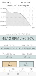
I've used the one for iphone called "RPM," which is cool because you can upload results to a searchable database to compare to others' results with the same turntable make/model. Lots of people question the accuracy of phone accelerometers for this purpose. Obviously analyzing the signal via a mic picking up a test tone is better, but I think phones are plenty useful for a basic benchmark.
On RPM app, my VPI Classic 3 reads 33.39, (+0.18%), W/F 0.14%
While the Technics does 33.34, (+0.03%), W/F 0.13%
Agreed, @jayme – minus the stylus drag, any deck SHOULD run fast. These were both taken absent any stylus drag (and with the Technics, I'm measuring a naked motor/platter just sitting on my desk - so it's also absent any resonance/oscillation rejection that a plinth might provide).
But to take that even further, consider that I'm comparing a relatively low-torque belt drive vs a much higher-torque direct drive. In theory, the more torque, the less sensitive to stylus drag—so who knows, these two tables may run at the exact same speed with that friction applied. In any case, we're talking tenths vs hundredths of one percent of an RPM... is that audible? I can't say.
But what I DO think is audible is wow & flutter. Groove friction varies as a record plays (music, not test tones) so a deck driven by an elastic belt might actually amplify W/F. Which I'm sure most people reading this already know is the #1 argument for Direct and Idler drive. When my Technics project is complete, I'll repeat the measurements with the same record/cartridge combo on both decks and we can compare.
Keep in mind alot of those phone W/F testing apps show the absolute RPM being off by a little, but the speed fluctuation measurements are typically dead on. This is the result I get measuring my SL1200MK2 with such an app. I cross checked it with other tachometers.

The coreless motor on the new Technics TT models is interesting. Its also funny how some audiophiles swear they can perceive "cogging" on the "inferior" SL1200 motor. When you ask them how they evaluate this, they have no concrete answer. Fact is the cogging force on the cored Technics SL1200MK2/3/4/5 is less than the spindle bearing friction. Its literally just a couple of grams and falls within the rumble spec. That is -80 dB or more down in level. I've worked with the Neumann VMS15 cutting lathe, which is speced on paper as having worse W/F. This is a popular cutting lathe which countless records are mastered on. So far, nobody has complained about the sound of it.
The coreless motor on the new Technics TT models is interesting. Its also funny how some audiophiles swear they can perceive "cogging" on the "inferior" SL1200 motor. When you ask them how they evaluate this, they have no concrete answer. Fact is the cogging force on the cored Technics SL1200MK2/3/4/5 is less than the spindle bearing friction. Its literally just a couple of grams and falls within the rumble spec. That is -80 dB or more down in level. I've worked with the Neumann VMS15 cutting lathe, which is speced on paper as having worse W/F. This is a popular cutting lathe which countless records are mastered on. So far, nobody has complained about the sound of it.
- Home
- Source & Line
- Analogue Source
- Rescuing & Reimagining a Technics SL-100c