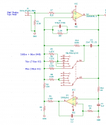
I have a reproduce EQ circuit here that I cannot figure out. Here's a .pdf of the Otari's service manual screen shot and the circuit I put into LT Spice. It is supposed to give an adjustable high frequency equalization; but in fact LT Spice says it just gives a HUGE low frequency boost. I have shown the circuit in LT Spice as it would occur in High Speed, with Q107 turned on and Q106 and Q108 off. What am I missing?
Attachments
Last edited:
> it just gives a HUGE low frequency boost.
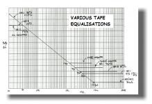
That's mostly what tape-play EQ does.
Stereo Lab - Tape equalisation correction
http://pspatialaudio.com/Tape EQs.png
The Otari seems to meet spec, at some point of trim.
That's mostly what tape-play EQ does.
Stereo Lab - Tape equalisation correction
http://pspatialaudio.com/Tape EQs.png
The Otari seems to meet spec, at some point of trim.
Attachments

Last edited:
That is the standard Otari tape equalizer circuit, it has switchable time constants for LF EQ (NAB/IEC) and two HF time constants, but I think you are missing part of the EQ which may appear in the next stage. (There is also a preceding stage in this particular design IIRC.) Massive LF gain and a shelving gain function determined by the HF time constant zero.
This isn't the LF compensator circuit which is normally a pretty cheesy baxandall bass control in the next stage.
I thought you were doing something like a state variable parametric EQ stage which is really closer to what is needed here.
And yes the only adjustments are the pots that set the HF corner frequency for each speed.
Something to note is that the frequency and amplitude of the head bump is speed dependent and should be different for each speed. The Otari heads are not particularly good in this regard either (at least the 2 track heads, but cannot generalize to your 8 track)
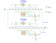
These are not public domain designs (they are mine) please feel free to use for personal use.
I've attached a capture of the front end amplifier stage in one of my tape amplifiers, and the LF compensator, you will note there is one for each speed and there are both multiple gain settings (attenuation only) and three different frequency options.
It does help, but the Otari heads would benefit from more sophisticated compensation, it is however unlikely the effort will be rewarded with results justifying the effort given the component and design quality of the rest of the deck.
Attachments
THANK YOU, PRR! My brain went on an unexcused holiday, and I forgot what I was dealing with---tape equalization!
Yes that is true---generally the head bump shifts down one octave when the speed is halved. At the moment I am dealing only with 15 ips, which is where I always run my Otari. Maybe I'll have to account for 7.5 ips later.Something to note is that the frequency and amplitude of the head bump is speed dependent and should be different for each speed. The Otari heads are not particularly good in this regard either (at least the 2 track heads, but cannot generalize to your 8 track)
Kevin, thanks for sharing your schematics---a quite elegant design! How flat were you able to get the low end?
I'm not sure for a variety of reasons. I can tell you with careful adjustment per the calibration procedure it should meet the Otari response specification on both speeds.
My test tapes have discrete test tones, and some sweeps, I have not had a lot of success doing response measurements with the sweeps, but I haven't really tried that hard either.
I was able to adjust the response on discrete tones to better match mid tones. The results depend heavily on the tone frequency, the control frequency selected and the head response.
The values shown are probably most appropriate for Otari 2 track heads as far as I know.
Strangely enough the Studer may provide me with sweeps that are usable and flat enough for setting the LF compensator.
I'm working on the next iteration of the pre-amp which is where my focus currently lies.
Hmmm...I only use test tapes to ballpark the LF settings; most don't have tones that address the real low end performance accurately. I just ballpark it then do the sweeping in record and THEN set the LF PB adjustment for flattest response.
Your comment about 7.5 ips being quite different in terms of LF bump got me thinking----my circuit tuned for 15 ips will be a total mess for the slower speed. So I'm going to just put in those same type of FET switches that Otari used to switch OUT my circuit @ 7.5. Problem is, I can't find the FETs they used--they're all obsolete! Can you direct me to a substitute for the P-channel (2SJ74 or 2SJ104) and N-channel (2SK 105 or 115 or 362) that are shown on the Otari schematic?
Your comment about 7.5 ips being quite different in terms of LF bump got me thinking----my circuit tuned for 15 ips will be a total mess for the slower speed. So I'm going to just put in those same type of FET switches that Otari used to switch OUT my circuit @ 7.5. Problem is, I can't find the FETs they used--they're all obsolete! Can you direct me to a substitute for the P-channel (2SJ74 or 2SJ104) and N-channel (2SK 105 or 115 or 362) that are shown on the Otari schematic?
Linear Systems makes suitable devices, give the LSJ74 a shot, note the gate to drain breakdown voltage rating of 25V and make sure you can't exceed it. LSK170 for the N channel device.
http://www.linearsystems.com/lsdata/datasheets/Copy_201175%20-%20LSJ74%20Rev%20A8%20dated%202019%2007%2024.pdf
They are expensive.
There should be commodity fets at DigiKey and Mouser that work well.
I would have thought the deck would already have these stages, you actually don't need any more of these for head bump correction. You need the sort of thing I show in my LF correction circuit.
The deck does have the HF repro circuit I have shown, plus a LF Compensation circuit that is really just a LF shelving filter. These allow you set the deck to be flat at 100Hz and 10KHz to match the repro level setting at 1 KHz. These do NOT, however, address the rather large LF bump---+2 db @ 65 Hz and -1.8db @ 130 Hz. THAT is what I am attempting to cure. Many other decks have a similar malady and is commonly referred to as 'contour effect' or 'secondary pole effect', as it evidently is cause by the secondary pole formed by the head geometry--the length of the pole face, the length of the face window, and the shape of the lamination behind the head face. (This is from the Nortronics paper on magnetic heads). My Studer A810, for instance, also shows some of this, but nowhere near as much as my Otari 1/2" 8-track; with my Ampexes being somewhere in between these two.
"There should be commodity fets at DigiKey and Mouser that work well."
That's what I was beginning to think as well, but there are so many its hard to choose--any suggestions? Also puzzling me is when I attempt to put in a pfet or nfet into LT Spice as a switch. Oddly enough, they do not behave as a near-zero pure resistance when the proper voltage is applied to the gate, as I had hoped, but as a nonlinear load that affects level as well as frequency response.😕
....pfet or nfet into LT Spice as a switch. Oddly enough, they do not behave as a near-zero pure resistance when the proper voltage is applied to the gate, as I had hoped, but as a nonlinear load that affects level as well as frequency response.😕
Show your work. We can't know if you are setting appropriate control voltage, polarity, signal level, circuit. Or what your expectation is. (And BTW, the slope is not "tape" but "wound head" correction). Compounded by the sketchy state of most audiotape literature (the NAB curve omits the slope and does not mention the fact).
I put the first JFET i found in a 2-decade old copy of a SPICE suite and quickly plotted from 135 Ohms at zero gate to mighty darn high at -3.3V gate. (It computed Gigs which is barely possible on plastic pack, certainly hard to confirm in real life, and totally moot around few-Kohm resistors.)
- Home
- Source & Line
- Analog Line Level
- Reproduce EQ circuit