The base problem is...its the PCL not the ECL...its sadly useless in my radios I do have few PCLs aswell. Also I dont believe there is no shipping cost to slovakia from there
An idel option would be for JJ starting production of ECL86. They could have
use in new production as head amp or driver tubes for 300B and as
replacement for old stuff.
But the market might be way to small for this.
Just remembered they have a driver tube for 300B's...Its the ECC99
Maybe the fully transistorized solution is the best, both with space ( it will fit whenever a
real ECL86 fits), and it will reduce heat somewhat as no filament is consumed.
It will also be much cheaper in component cost.
Two boards, one with the tube socket, and one standing up at one side with all but
one transistors ( the power one is mounted on a L-formed sheet as long as the ECL86
and acting as cooler)
Despite of all the adapters needed and all that effort, this EL84/ECC83 solution can't be regarded as a real ECL86 subtitution. Yes, the EL84 datasheets read operating points with only 9 watts of plate supply instead of 12 watts, but in comparison with the ECL86 pentode or the EL41 needs to be biased more negatively (higher cathode resistor, 210 v.s 170 ohms).
Even though they're also not produced anymore, I think the PCL86 would be the best replacement still - same pinout, same data. The heater could be supplied via a voltage doubler from the original 6.3 Vac heater winding.
Best regards!
Even though they're also not produced anymore, I think the PCL86 would be the best replacement still - same pinout, same data. The heater could be supplied via a voltage doubler from the original 6.3 Vac heater winding.
Best regards!
Yeah I really dont have an idea how would I replace the ECL86 PROPERLY with semiconductors but I assure you it wont be one transistor...rather a array of jfets and a darlington. Ofcourse the controll section would be on SMD and the power transistor would be on a separate heatsink... But it would still require A LOT of work to properly emulate the ECL86. Regardless it would be a ECL86 with very low distortion figures and it would also ommit G3 (simply the pin wont be hooked up into the emulating circuit). That could pose an issue with UL amps and some weird modulatin tube stuff (some awkward connections with awkward radios and awkward setups). So it wouldnt be a fully valid substitute. However the though of making a solid state tube is interesting to me..maybe Ill try something in the future.
But I dont think it would be tomorrow or any time soon. Above all I dont know how to use LT spice so thats a major setback. I have designed stuff before without it so given enough time I can work it out via tria and error.
But I dont think it would be tomorrow or any time soon. Above all I dont know how to use LT spice so thats a major setback. I have designed stuff before without it so given enough time I can work it out via tria and error.
I think you mean g2, because g3 is the suppressor grid, which in the ECL86 is internally connected to the cathode.
I am curious. Can you please give an example of the ECL86 being used in 'some weird modulatin tube stuff'?
I am curious. Can you please give an example of the ECL86 being used in 'some weird modulatin tube stuff'?
No. I cannot show you an example. But I bet you there will be that one oddball design that will be playing with with the grids (likely not in audio circuits).
Replication of how g2 affects the plate current is doable ( it will affectYeah I really dont have an idea how would I replace the ECL86 PROPERLY with semiconductors but I assure you it wont be one transistor...rather a array of jfets and a darlington. Ofcourse the controll section would be on SMD and the power transistor would be on a separate heatsink... But it would still require A LOT of work to properly emulate the ECL86. Regardless it would be a ECL86 with very low distortion figures and it would also ommit G3 (simply the pin wont be hooked up into the emulating circuit). That could pose an issue with UL amps and some weird modulatin tube stuff (some awkward connections with awkward radios and awkward setups). So it wouldnt be a fully valid substitute. However the though of making a solid state tube is interesting to me..maybe Ill try something in the future.
But I dont think it would be tomorrow or any time soon. Above all I dont know how to use LT spice so thats a major setback. I have designed stuff before without it so given enough time I can work it out via tria and error.
the current as the g1 will at a higher potential). But how the g2 will
draw current depending of plate etc is more tricky. Maybe one could ignore that.
I would likely ditch everything and make it a triode. Really with semiconductors you can introduce far less distortion than you would with tubes so I dont think any UL or pentode connection would make sense. Since you could just ditch the drawbacks of the tube and live with the transistors that are likely more linear than the tubes. No need for that extra grid.
Btw if it were to happen I would not give a damn about replicating the ECL86's linearity completely. Pointless and too difficult. I would not be going that far..no reason. I just want my radios to work soo yeah. I want the tubes to bias up properly and thats all.
Btw if it were to happen I would not give a damn about replicating the ECL86's linearity completely. Pointless and too difficult. I would not be going that far..no reason. I just want my radios to work soo yeah. I want the tubes to bias up properly and thats all.
Triodes are the most linear device !!I would likely ditch everything and make it a triode. Really with semiconductors you can introduce far less distortion than you would with tubes so I dont think any UL or pentode connection would make sense. Since you could just ditch the drawbacks of the tube and live with the transistors that are likely more linear than the tubes. No need for that extra grid.
Btw if it were to happen I would not give a damn about replicating the ECL86's linearity completely. Pointless and too difficult. I would not be going that far..no reason. I just want my radios to work soo yeah. I want the tubes to bias up properly and thats all.
As for g2 i's really a useful tuning device.
Don't forget that the goal of this thought-experment is to replace ECL86 in
a real amp - thus it has to behave exactly as a ECL86 . It's no use making
a device that won't fit in the shoes of an ECL86.
However, this could be seen as an excersice in electronics, it won't pay back
the investment. In spite of that it would be a challange !
You have just hit the nail dead on head on.
I dont see any reason to bother wasting my resources and time (i already have too many projects going on). I just want my radios to work and thats it. And you will never be able to properly replicate the tube simply for the fact that every tube is different.
I dont see any reason to bother wasting my resources and time (i already have too many projects going on). I just want my radios to work and thats it. And you will never be able to properly replicate the tube simply for the fact that every tube is different.
An example of a solid state replacement for the PL802 (video tube to drive the CRT in TV's) which at the end of the tube era was scarse. Only two transistors, and with g2:
https://frank.pocnet.net/sheets/084/p/PL802S.pdf
https://frank.pocnet.net/sheets/084/p/PL802S.pdf
Last edited:
Good point, PCL200, als this was my idea also!
Btw, I wonder why this once really scarce and expensive tube is easily obtainable these days - still, of course 😕.
Best regards!
Btw, I wonder why this once really scarce and expensive tube is easily obtainable these days - still, of course 😕.
Best regards!
Hi Kay,
I waited a bit to see if this weird thread continued. But alas...
You are right, the current prices (in my country about Euro 8 for a NOS one) are difficult to combine with the alledged scarcity of them. Maybe the real reason is different? Like them going bad too fast?
I waited a bit to see if this weird thread continued. But alas...
You are right, the current prices (in my country about Euro 8 for a NOS one) are difficult to combine with the alledged scarcity of them. Maybe the real reason is different? Like them going bad too fast?
Last edited:
I suppose the PL802 became scarce when tube powered colour TV sets were still around, as this tube was designed to drive the three paralleled CRT cathodes directly. This issue decreased with the advent of sufficiently powerful video transistors and finally vanished with flat panel display TV's. So there's still some - limited - stock of NOS tubes nowadays no one has any use for.
Best regards!
Best regards!
A 6v6 solid state replacement was featured on the april 2001 Electronics World issue. The heatsink on the magazine picture looks to be severely undersized for passive cooling.
The PL802 tube was still used on hybrid TV sets in the '70, when tube manufacturing was already shutting down. Perhaps Philips marketed the solid state replacement to meet a demand from manufacturers who still had to sell older chassis.
The PL802 tube was still used on hybrid TV sets in the '70, when tube manufacturing was already shutting down. Perhaps Philips marketed the solid state replacement to meet a demand from manufacturers who still had to sell older chassis.
Attachments

Sounds like a good explanation, pcan.
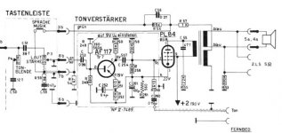
I found this hybrid replacement for a PCL86 on the Radiomuseum.org site. With an EL86 (which is code-wise strangely enough equivalent with PL84 and UL84, except for the heater voltage/current) it could substitute for an ECL86, as long as B+ is not too far of the 190 V in the schematic (or if you adapt the schematic for higher B+).
I found this hybrid replacement for a PCL86 on the Radiomuseum.org site. With an EL86 (which is code-wise strangely enough equivalent with PL84 and UL84, except for the heater voltage/current) it could substitute for an ECL86, as long as B+ is not too far of the 190 V in the schematic (or if you adapt the schematic for higher B+).
Attachments
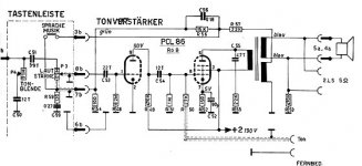
These schematics appear to belong to (supposedly Philips?) TV sets of different generations and should not be considered as a substitution advice, as the plate loads are rather different for both tubes.
Best regards!
Best regards!
I agree.
Pentodes need roughly Vak / Ia as a load. In the original schematic with the PCL86 the cathode current of the L-section is about 39 mA, in the replacement the cathode current of the PL84 is 33 mA, which is close enough.
With higher B+ (for an ECL86 in a radio a B+ of 250 V is more likely) the schematic probably needs some adaptation to keep close to the Vak / Ia rule of thumb.
Edit: Your proposal to use the PCL86 with a voltage doubler as the solution for the different filament voltage and current, is by far the best. But how to get the bridge rectifier and capacitors in an adapter of reasonable size? Maybe by putting the voltage doubler in a little seperate box which is attached with a four prong cable to the than simple adapter so you can always find room for the voltage doubler in any radio?
Last edited:
- Home
- Amplifiers
- Tubes / Valves
- Replacing the ECL86/PCL86 with two tubes