If you don't want the high ESR, as in woofer/mid circuits as it can take the life out of the sound, this is the answer. ECI stretches the film more to make a tighter roll and fit more layers in the can.
Oh, and the price was reasonable at $40 each. You can't buy some power supply caps for that price.
Oh, and the price was reasonable at $40 each. You can't buy some power supply caps for that price.

Perry, I've been studying the three different notch filter approaches to the woofer low pass that you've presented for some time now and I think I've learned a lot, but I'm a bit stuck. I am working on a Xover for the Fostex FW305 woofer and a 800 hz. horn and compression driver and I can't decided which filters you've shown would be the best approach.
I have really enjoyed VituixCAD and I have found the simulations are making very good predictions and I am enjoying iterating circuits and letting the sims show me what's happening, even if I don't completely understand, and I'm trying to intelligently stumble upon something, while also trying to get a feeling for some fundamentals. But, I am a bit stuck trying to learn for the strategies you've shown and just stumbling around until I find something that appears to work. I guess I might just need some encouragement if an easier answer isn't lying at hand.
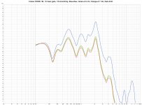
I have seen in the Sims and in some brief experiments that a Zoebel on the woofer profoundly influences the effect of filter elements like the low pass inductor coil. See the raw response and the response with some coils of the FW305 below. And, this effect is apparent with other elements as well, like the parallel LCR element notch placed in series with the woofer. I think this is what you used on Bitches Eminence woofer. The notch doesn't show any effect without the Zoebel, or maybe also a resistor in series as well, or some combination.
That's okay I guess, but given I am trying to evolve to a minimalist Xover, in the spirit of your notch filter approach to woofer Xover. I think this is particularly appropriate for this woofer. I've built a 2nd order Xover with Zoebel on the woofer that appears to work quite well. But, I really had to hammer the LP slope to get the 2200 hz peak of the FW305 tamed. It's quite pronounced and is very strong off axis as well. The 2nd order on the woofer and maybe 3rd on the horn get the phase lined up nicely and a good response, but it's a lot going on to get these measures looking okay and it's like the Xover tends to evolve to just one frequency that will work and I have to take it or else all else falls apart.
I really like using an L-Pad on the horn for attenuation and I'd like to experiment with a minimal first order filter to see just how much musicality I can get from the horn, and the combination of L-Pad and capacitor appears to be plenty of control over the final acoustic slope. But, the woofer is tough with that peak. And, otherwise I think this woofer has some nice sound, so I want to see what sound I can get with it as well with minimal components. I think I like the paper cone of this woofer, which is also why I have this 2200 peak. I have paper diaphragms in my compression driver, so I'm really trying to hear the tonality of these drivers to learn how to differentiate amongst them.
In conclusion, and sorry so long, but at the core of all this is a pebble in my shoe. I have read so much research on why the woofer's voice coil inductance causes problems, and maybe why the Zoebel helps, Marshall Leach, etc. and it appears that VituixCAD is simulating this, but for the life of me, I can't see where or how VituixCAD is getting an inductance value for the woofer coil. That value is in the header of the Z files I upload from DATS, and I think I've seen where there are settings in the Enclosure tool, even for advanced Z modeling, but I'm at a complete loss to understand how it's apparently simulating this in the crossover simulation unless it's parsing the text of the header of the Z file from DATS. I've also read so many ideas from people about when it's appropriate and when not, for example profiguy on this thread, also Wayne Parham but I can't really get their suggestions to work in practice. I know these guy really know this stuff, so I can't just dismiss it. Either I try to remove it and the filter falls apart, or I see so many people suggesting it's something to be avoided for best sound. I can see you are sometimes using it, sometimes not, but I'm not sure why.
Any suggestions would be greatly appreciated. Until then, I'm really trying to iterate in VituixCAD and then iterate in listening, but blind alleys are several hours of work.
Cheers,
Jamie
I have really enjoyed VituixCAD and I have found the simulations are making very good predictions and I am enjoying iterating circuits and letting the sims show me what's happening, even if I don't completely understand, and I'm trying to intelligently stumble upon something, while also trying to get a feeling for some fundamentals. But, I am a bit stuck trying to learn for the strategies you've shown and just stumbling around until I find something that appears to work. I guess I might just need some encouragement if an easier answer isn't lying at hand.
I have seen in the Sims and in some brief experiments that a Zoebel on the woofer profoundly influences the effect of filter elements like the low pass inductor coil. See the raw response and the response with some coils of the FW305 below. And, this effect is apparent with other elements as well, like the parallel LCR element notch placed in series with the woofer. I think this is what you used on Bitches Eminence woofer. The notch doesn't show any effect without the Zoebel, or maybe also a resistor in series as well, or some combination.
That's okay I guess, but given I am trying to evolve to a minimalist Xover, in the spirit of your notch filter approach to woofer Xover. I think this is particularly appropriate for this woofer. I've built a 2nd order Xover with Zoebel on the woofer that appears to work quite well. But, I really had to hammer the LP slope to get the 2200 hz peak of the FW305 tamed. It's quite pronounced and is very strong off axis as well. The 2nd order on the woofer and maybe 3rd on the horn get the phase lined up nicely and a good response, but it's a lot going on to get these measures looking okay and it's like the Xover tends to evolve to just one frequency that will work and I have to take it or else all else falls apart.
I really like using an L-Pad on the horn for attenuation and I'd like to experiment with a minimal first order filter to see just how much musicality I can get from the horn, and the combination of L-Pad and capacitor appears to be plenty of control over the final acoustic slope. But, the woofer is tough with that peak. And, otherwise I think this woofer has some nice sound, so I want to see what sound I can get with it as well with minimal components. I think I like the paper cone of this woofer, which is also why I have this 2200 peak. I have paper diaphragms in my compression driver, so I'm really trying to hear the tonality of these drivers to learn how to differentiate amongst them.
In conclusion, and sorry so long, but at the core of all this is a pebble in my shoe. I have read so much research on why the woofer's voice coil inductance causes problems, and maybe why the Zoebel helps, Marshall Leach, etc. and it appears that VituixCAD is simulating this, but for the life of me, I can't see where or how VituixCAD is getting an inductance value for the woofer coil. That value is in the header of the Z files I upload from DATS, and I think I've seen where there are settings in the Enclosure tool, even for advanced Z modeling, but I'm at a complete loss to understand how it's apparently simulating this in the crossover simulation unless it's parsing the text of the header of the Z file from DATS. I've also read so many ideas from people about when it's appropriate and when not, for example profiguy on this thread, also Wayne Parham but I can't really get their suggestions to work in practice. I know these guy really know this stuff, so I can't just dismiss it. Either I try to remove it and the filter falls apart, or I see so many people suggesting it's something to be avoided for best sound. I can see you are sometimes using it, sometimes not, but I'm not sure why.
Any suggestions would be greatly appreciated. Until then, I'm really trying to iterate in VituixCAD and then iterate in listening, but blind alleys are several hours of work.
Cheers,
Jamie
Attachments
The only way you can deal with that peak is with a notch filter. You need a very simple LCR notch filter and you also probably need a RC Zobel.
BTW you don’t even need a low pass. Just the notch to take out that peak.
BTW you don’t even need a low pass. Just the notch to take out that peak.
Should the LCR be in series with the woofer, (LCR components in parrallel), or as a series of LCR components conjugate to the woofer? I guess I can try both, but while we're here, I'm really curious if you have a preference.
And thanks for the suggestion for not needing a low pass, I was hoping to do that as well, just use the impedance wall of the woofer after the cone breakup peak is attenuated enough. Then bring the horn to match it.
And thanks for the suggestion for not needing a low pass, I was hoping to do that as well, just use the impedance wall of the woofer after the cone breakup peak is attenuated enough. Then bring the horn to match it.
Connect a resistor in series with a capacitor.
Put that pair in parallel with the woofer.
Now you have a zobel.
Connect an inductor, capacitor and resistor in parallel with each other. That's a notch filter.
Wire that combo in series with the [woofer + zobel].
Model them in Vituixcad until they behave the way you want.
Put that pair in parallel with the woofer.
Now you have a zobel.
Connect an inductor, capacitor and resistor in parallel with each other. That's a notch filter.
Wire that combo in series with the [woofer + zobel].
Model them in Vituixcad until they behave the way you want.
Thank you! Sorry to have you spell it out for me. I really do appreciate the explicit suggestion on top of the full tutorial. I’ll report back.
Cheers, Jamie
Cheers, Jamie
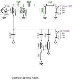
Well, I tried to get away with a notch on the woofer at 2200 hz, the cone breakup frequency of the FW305, with a minimal first order or simple coil only filter on the woofer, but I just couldn't get it to work. Not saying it wouldn't, but I felt I was fighting a practical reality that includes my inexperience and that I should follow a more traditional route and get something that sums okay at 1600 hz. That's 2X my horn cutoff and I think far enough below the woofer cone breakup.
But, I tried the VituixCAD optimizer for the first time and really enjoyed the trip. Given the additional components of a 2nd order, Zoebel and notch on the woofer, I was happy to let the optimizer iterate a solution instead of me trying to use some kind of amateur network analysis approach. Some of the values are a bit surprising to me, but they appear to work and I don't think I'd ever gotten there on my own.
I've been liking Wayne Parham's 2nd order on the woofer and 3rd order on the tweeter approach, and it turned out both drivers are in phase at Xover with the optimized Xover. I'll deal with the excess response at 1500 hz of the simulated on axis response after I get some measurements.
Thanks for all the help.
Jamie
Attachments
-
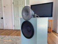 IMG_2306.JPEG357.9 KB · Views: 60
 -
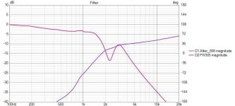
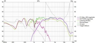 808andFW305_1600hz_2200hzNotchV1_SPL.jpg63.8 KB · Views: 47
 -
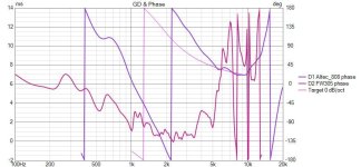 808andFW305_1600hz_2200hzNotchV1_Phase.jpg61.3 KB · Views: 43
 -
 808andFW305_1600hz_2200hzNotchV1_Filter.jpg56 KB · Views: 42
 -
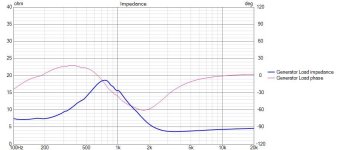 808andFW305_1600hz_2200hzNotchV1_Imp.jpg52.1 KB · Views: 42
 -
 808andFW305_1600hz_2200hzNotchV1.jpg19.7 KB · Views: 58
You need to flip your tweeter lpad. The parallel resistor goes across the driver after the series resistor.
Oops. Yes, thanks. I don’t know why I put it that way in sim. At least I can fix and rerun the optimizer.
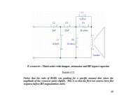
Sorry, again, NO, the L-Pad is correctly configured. Or, at least it is exactly as I intended. I do not know why it should be this way, or the way you are suggesting, but Wayne Parham of Pi Speakers has documented the configuration of the L-Pad and the conjugate dampening resistor connection to the tweeter extensively in the two white papers he's published on his website. These papers explore the function of the conjugate resistor using Spice models and Wayne compares the operation of the conjugate resistor in this configuration to series resistors alone or Zoebel dampeners, alone, etc.
Unfortunately, I do not recollect a direct comparison between the conjugate resistor configured as I have done here and as Wayne has recommended to the configuration that you are suggesting. It would be interesting to see someone explore this. For now, I have no reason to second guess Wayne's work.
https://www.pispeakers.com/Speaker_Crossover.pdf
Maybe the differences in L-Pad configuration are confused by the terminology. I can see that the L-Pad circuit that is described by Vance Dickason in Loudspeaker Design Cookbook uses the configuration that Wolf recommends. Vance uses extensive citations to journal articles for most of the material, but for his description of an "L-Pad" he cites an article by M. Knittel "Microcomputer-Aided Driver Attenuation" in Speaker Builder, 1/85.
Wayne says that his configuration "is known as a resistor damped compensation network." and Wayne's emphasis in his exposition in this filter topology includes emphasis on damping compression drivers on horns and also filter induced resonances. So, this makes sense.
Maybe folks borrow the circuit topology too strictly from L-Pads that are wipers on carbon traces with a knob?
Neither is "right" or "wrong." You can do it either way, but when you switch the positions of those resistors and tweak the values as necessary, the output is less influenced by the tweeter's impedance curve. I suggest modeling it both ways to see what you get.
Thanks Perry for considering this. I was able to find a more comprehensive explanation about the Pi circuit from Wayne on his forum that might be useful. I used Wayne's design because it is a complete treatment of the unique requirements of compression drivers as tweeters, including the option for top octave compensation. I guess we are far away from the original topic of woofer notch filters, but I want to follow up on advice received as best I can. And, I think Wayne's work is amazing with respect to educating the DIYer.
A short excerpt from the forum posting goes like this.
Question: "2 - On the xover attenuations you use on the compression drivers (R1 & R2), you use (pardon me if you answer this question before) R2 before R1. Is this for the better protection of the drivers, since R1 and driver would be in series? I am using a similar attenuation w/compensation but R2 comes after R1 + Cap. Do you think there is any problem with that, providing the right calculations (and testing on spice)?"
Answer: "You could rearrange the R1/R2 values or use an L-Pad as additonal output shunt, in position Rs, after the R1/R2/C1 network. I've seen people do it, some with good results. However, I always recommend against it for best results. The reason is simple: Compression drivers need 6dB/octave HF equalization for a total of 8dB to 12dB boost overall. So any padding you might provide outside the compensation network would reduce the level of top-octave augmentation available. Use Rs to swamp driver impedance peaks, if necessary, but not for additional padding."
https://audioroundtable.com/forum/index.php?t=msg&th=10656&goto=53182&#msg_53182
Attachments
Yes, if you use the original schematic and bypass the resistor with a capacitor you'll get more top octave augmentation. Maybe 1-3dB I'm guessing.
The tradeoff is that the impedance peak of the compression driver will also be impressed on the response curve, because the R1 resistor reduces the damping at resonance and increases the Q. This is less of a problem with my suggested schematic.
You can decide which priority is more important.
The tradeoff is that the impedance peak of the compression driver will also be impressed on the response curve, because the R1 resistor reduces the damping at resonance and increases the Q. This is less of a problem with my suggested schematic.
You can decide which priority is more important.
- Home
- Loudspeakers
- Multi-Way
- Replacing Standard Low Pass Xovers with Notch & Shelf Filters