The most common crossover problem in the world is taming cone breakup and removing peaks from woofer response.
Many designers use 18dB and 24dB crossovers simply because they have to get rid of a peak and they don't have a better way to do it. But in general I don't like steep filters. All other things being equal (which of course they rarely are) I think shallow filters sound better to my ear.
My philosophy as a designer is "don't use brute force when finesse will do" and "don't use nuclear weapons when you can use a bow and arrow."
One of my favorite ways to get around this is with shelf and notch filters. At the Parts Express Midwest Audiofest in August, I won a pair of Ciare HWG160-4 woofers. These are excellent drivers. Like most woofers they have some peaking at the high end. This is the Ciare spec sheet:

In a bass reflex box in my room, data imported into VituixCad, the response looks like this, below:

A 6dB filter would level the response overall, but you'd still get that peak at 5-6kHz showing up in the response.
Most folks, then, would apply a low-Q 12dB filter. That would work just fine, but a 12dB filter adds to the driver's 12dB rolloff making a 24dB/octave final slope which has 360 degrees of phase shift. I feel that is undesirable. Given that the woofer is already 2cm behind the tweeter physically, it adds group delay and makes the crossover integration even more difficult.
A notch filter is a more gentle approach.
Schematic:

Signal at driver terminals:

Above is the drive signals at the woofer and tweeter terminals. You see a notch filter at 5.5kHz which cancels out the peak without adding even more phase shift at higher frequencies.
You might think that the -35dB depth of the notch is too much, and initially I did too. But when experimenting with real life measurements I found that it minimized interference with the tweeter.
Below is the schematic of the filter. I have a zobel across the woofer terminals, and a 4 ohm resistor in series with a 0.75uF capacitor, and those are in parallel with the 1.2mH inductor:

As you see above, I get a flat response up to 2K and a very nicely behaved downward taper above that point.
The tweeter is a SB Acoustics SB29BNC. The total circuit and modeled response are below:

The actual measured response of the system, at 1M distance in my room (no gating or attempt to reduce reflections) is here:

These speakers sound fantastic. The woofers reach down to 35Hz in an 18 liter reflex box. 86dB SPL. The tweeters have all of the holographic imaging and detail you'd expect from an SB Acoustics beryllium tweeter. They have precise 3D imaging and a "high resolution monitor" sound signature.


I chose off the shelf Iwistao cabinets https://www.iwistao.com/collections...15l-for-tube-amplifier?variant=31964739993715 - Iwistao will custom cut the driver openings for you before they ship, and it took less than 2 weeks from order to delivery. The build quality is not impeccable - you can see a tiny little mark just above the speaker grille socket for example - but the quality is quite good and the speakers are beautiful.
Many designers use 18dB and 24dB crossovers simply because they have to get rid of a peak and they don't have a better way to do it. But in general I don't like steep filters. All other things being equal (which of course they rarely are) I think shallow filters sound better to my ear.
My philosophy as a designer is "don't use brute force when finesse will do" and "don't use nuclear weapons when you can use a bow and arrow."
One of my favorite ways to get around this is with shelf and notch filters. At the Parts Express Midwest Audiofest in August, I won a pair of Ciare HWG160-4 woofers. These are excellent drivers. Like most woofers they have some peaking at the high end. This is the Ciare spec sheet:
In a bass reflex box in my room, data imported into VituixCad, the response looks like this, below:
A 6dB filter would level the response overall, but you'd still get that peak at 5-6kHz showing up in the response.
Most folks, then, would apply a low-Q 12dB filter. That would work just fine, but a 12dB filter adds to the driver's 12dB rolloff making a 24dB/octave final slope which has 360 degrees of phase shift. I feel that is undesirable. Given that the woofer is already 2cm behind the tweeter physically, it adds group delay and makes the crossover integration even more difficult.
A notch filter is a more gentle approach.
Schematic:
Signal at driver terminals:
Above is the drive signals at the woofer and tweeter terminals. You see a notch filter at 5.5kHz which cancels out the peak without adding even more phase shift at higher frequencies.
You might think that the -35dB depth of the notch is too much, and initially I did too. But when experimenting with real life measurements I found that it minimized interference with the tweeter.
Below is the schematic of the filter. I have a zobel across the woofer terminals, and a 4 ohm resistor in series with a 0.75uF capacitor, and those are in parallel with the 1.2mH inductor:
As you see above, I get a flat response up to 2K and a very nicely behaved downward taper above that point.
The tweeter is a SB Acoustics SB29BNC. The total circuit and modeled response are below:
The actual measured response of the system, at 1M distance in my room (no gating or attempt to reduce reflections) is here:
These speakers sound fantastic. The woofers reach down to 35Hz in an 18 liter reflex box. 86dB SPL. The tweeters have all of the holographic imaging and detail you'd expect from an SB Acoustics beryllium tweeter. They have precise 3D imaging and a "high resolution monitor" sound signature.
I chose off the shelf Iwistao cabinets https://www.iwistao.com/collections...15l-for-tube-amplifier?variant=31964739993715 - Iwistao will custom cut the driver openings for you before they ship, and it took less than 2 weeks from order to delivery. The build quality is not impeccable - you can see a tiny little mark just above the speaker grille socket for example - but the quality is quite good and the speakers are beautiful.
Last edited:

I provide a 2nd example of the "Notch Filter instead of Low Pass" approach in my thread for the Walnut Dipoles:
https://www.diyaudio.com/community/threads/the-walnut-dipoles.404187/post-7482010 - this is worth a close look.
And here is a 3rd example:
The SB Acoustics 15OB350 Open Baffle woofer has a raw response in an Open Baffle enclosure that looks like this:

Above, all of the crossover components are removed and this is the raw 1/12 octave response of the woofer in a real cabinet and real room.
I want to tame the peak at 450Hz and I want to cross over to a tweeter at 1200Hz without brute force. I can do this with 2 notch filters in series. This circuit also includes a Marshall Bass Boost passive LC filter which adds 7dB at 40 Hz:

This circuit is much better behaved than a traditional low pass filter and will integrate with a constant directivity HF driver seamlessly. The peak at 40Hz will diminish with larger distances from the speaker (this measurement was made at 1M and dipoles have a proximity effect that the +7dB peak is compensating for).
https://www.diyaudio.com/community/threads/the-walnut-dipoles.404187/post-7482010 - this is worth a close look.
And here is a 3rd example:
The SB Acoustics 15OB350 Open Baffle woofer has a raw response in an Open Baffle enclosure that looks like this:
Above, all of the crossover components are removed and this is the raw 1/12 octave response of the woofer in a real cabinet and real room.
I want to tame the peak at 450Hz and I want to cross over to a tweeter at 1200Hz without brute force. I can do this with 2 notch filters in series. This circuit also includes a Marshall Bass Boost passive LC filter which adds 7dB at 40 Hz:
This circuit is much better behaved than a traditional low pass filter and will integrate with a constant directivity HF driver seamlessly. The peak at 40Hz will diminish with larger distances from the speaker (this measurement was made at 1M and dipoles have a proximity effect that the +7dB peak is compensating for).
Last edited:
You also have to realize that the ripple using notches like this will allow tweeter bandwidth back through the woofer by essentially bypassing the lowpass filter. Using the filter as you described before the passive boost was added will allow this to occur. This is why that capacitor should really not exceed 1uF in most cases. This can also lead to low impedance issues if it is too large.
Then there is the audibility threshold of the suppressed frequencies. If using a notch as described initially, this a lot of times produces an LR4 acoustic rolloff inherently. In the same process it is easy to reduce the offensive frequencies to the bare minimum -25dB, or the generally preferred -40dB.
While I respect your preference for lower order slopes, problem suppression still has to be achieved with benign system loads, and the methods usually make steeper slopes while getting there.
I’ve done numerous versions of this,both passive and active; if you study the Live Edge Dipoles and Bitches Brew, both employ it. I’ve found letting in frequencies >5khz reach woofers is usually not a problem.
The woofer is already rolling off 12dB / octave and that’s usually enough. The lower phase shift makes crossover integration easier.
The woofer is already rolling off 12dB / octave and that’s usually enough. The lower phase shift makes crossover integration easier.
This is an interesting paper that supports (prefers) series notch over parallel notch filters:
https://purifi-audio.com/blog/app-notes-2/low-distortion-filter-for-ptt6-5x04-naa-11
https://purifi-audio.com/blog/app-notes-2/low-distortion-filter-for-ptt6-5x04-naa-11
I'd say replacing a low pass filter with a notch filter is how most true 1st order acoustic slopes are achieved. if you are wanting higher order slopes, then notches are probably not as economical.
I'm purely talking about LP filter effect and not the requirement to notch breakup and reduce harmonic distortion lower down.
I'm purely talking about LP filter effect and not the requirement to notch breakup and reduce harmonic distortion lower down.
The Diyaudio Store has the circuite board for a cheap fullrange
equalizer to take care of any high frequency peak and the ability
of adding some bass boost. This circuite uses the verry cheap J113
jfets but to get good preformance from them they need to be matched
not just to each other but to a pair of resistors so just those matched
parts are included with the very cheap circuite boards but for $10 a
pair what do you expect !
https://www.diyaudio.com/community/threads/full-range-eq.399413/
Sort of. It recommends a high impedance parallel notch in series with the driver (after other elements) for attenuating major stopband resonances & reducing the resonant amplified HD products caused in the passband. This is something a few of us have done for a number of years, and can work extremely well. Other than for that very specific purpose, they don't (AFAIK) prefer either beyond 'whatever is needed for the application'.This is an interesting paper that supports (prefers) series notch over parallel notch filters:
https://purifi-audio.com/blog/app-notes-2/low-distortion-filter-for-ptt6-5x04-naa-11
I would do whatever it takes to achieve a fairly smooth phase response and make sure it extends well into the overlapping responses of other drivers up to 25 - 30 dB down in amplitude past the filter cutoffs. Same holds true for rolloff slopes, which need to be smooth if the design is to sound as good as the drivers are capable of. This is where skilled prioritizing of cost vs performance decisions come into play regarding xover component choices.
The larger value series components in the xover will affect SQ the most, specifically the LF inductors and HF high pass caps. Large cored inductors have the most potential negative affect. Always choose a higher grade core (air is best) over the absolute lowest DCR. If the HF driver can support a more shallow slope, I'd prefer this, coupled with a notch filter over just using a steeper slope in hopes of keeping peaks sufficiently attenuated out of band without the use of notch filters. If you have multiple peaks, perhaps you need to choose a more suitable driver or use mechanical means to suppress the peak depending on its origin. Stiff cones are great for bass, but usually break up badly in the midrange. Pick your poison, but don't expect that 10 - 15 dB peak to be inaudible with just a 2nd order LP regardless of how low in cutoff it is. You'll always hear it once you know its there - at least I do.
The other critical decision is where to place the notch filter in respect to the HP or LP group of components. This can have unexpected and detrimental results in final speaker voicing due to interaction with impedance fluctuations in the drivers. The same holds true for HF level pads. Their affect on tweeter performance is greater than many think. I try to avoid using just a series resistor for this purpose, as its too sensitive to the HF impedance fluctuation. Always use a parallel resistor to achieve a true voltage splitter for this purpose and place it just before the tweeter (and zobel, if you use one).
I believe in using zobels on HF drivers which permit the best linearity the tweeter is capable of and to maintain flatter phase and impedance response well past the upper tweeter cutoff. This makes a big difference in holographic imaging and vertical staging of instruments. The rising impedance of most HF drivers will create an unnatural broad HF peak, which is not pleasant and.fatiquing on the ears. Its best to linearize tweeters with sharp rising HF response to avoid sibilance and sizzle, especially with MM phono carts. Its very hard on the ears with longer listening sessions.
If the tweeter has a tall, sharp VHF amplitude breakup mode (usually around 25k on most metal domes), it's best to suppress it if you can measure it reasonably accurately or have reliable FR data to go by. Depending on the source material played back, the breakup resonance can affect lower treble odd order HD, especially with lower tweeter HP frequencies. Some swear they can't perceive this, but my research has shown me its very noticeable with certain music once the ear has drawn attention to it.
Lastly, the integration of zobels into LF and MF lowpass filters isn't a good idea, since it contorts phase response in attempts to linearize FR. This again will ruin the phase outside of the driver's pass band while deteriorating driver integration. This often gets overlooked and mis-prioritzed due to the common attitude that anything past 24 dB or so attenuation (while still in range of overlappimg driver) won't be perceptible even when there are significant anomalies in phase and timing in the overlap region. It's still very audible when both drivers combine and abruptly shift the stereo image around - likely the most noticeable side affect. This is why I dont like mixed filter slopes, unless they add up correctly with the filtered driver to form the same acoustical end slope ( and phase shift) as the neighboring driver.
Finally, trying to combine a ported enclosure with a subwoofer is always going to sound weird and cause significant in room low end response variations which are tough to correct considering more than one listening location. This is a big one for me. I'd rather not have the LF extension if it means dealing with chaotic in room LF response. If you want (or need to) run subs, always use sealed mains enclosure designs.
In the end, the range from 300 hz to 10 kHz is the most critical band where phase should stay smooth and with gradual trend moving in one directional for the most natural and lifelike reproduction of music. If that isn't the case, you won't hear your music as acoustically correct as it can be (aside from the usual studio trickery used to make multitrack recordings artistically engaging and artificially hyped).
Its not necessarily flat phase being all out important here, but rather the gradual trend of smooth phase response change over a given frequency range. IOW its relative (comparative) phase being important, more than absolute phase itself.
I hope this all made sense.
This is an interesting paper that supports (prefers) series notch over parallel notch filters:
https://purifi-audio.com/blog/app-notes-2/low-distortion-filter-for-ptt6-5x04-naa-11
This is the ONLY passive method of dealing with difficult sharp resonance modes in metal or other stiff cone material drivers. Employing both source and sink notch filter types will guarantee the speaker won't end up being overly sensitive to various amplifier types. Impedance dips can radically change the speaker's acoustic personalities and show more distortion in the lowest areas in the curve.
I've had countless discussions with some very seasoned speaker designers who were adamant cascaded notch filters were overkill to get decent results from very difficult to work with drivers that otherwise had very well designed motors and cone compositions. Very rarely have I come across a very good sounding 2 way speaker without at least one set of notch filters.
@perrymarshall I’m following your lead here. I’ve built a few speakers now. Mostly subwoofers and full range variations. In my current build which I plan to get to the point where I can measure it over the next couple of weeks I’m expecting to have to deal with a similar notch to yours, but the peak is about 10db up at 7k hz.
I’ve looked at online calculators like this one but I’m surprised that they don’t account for load impedance. Is it really as simple as popping peak value in? The woofer is 2 css Ldw7 wired in parallel.
http://www.learningaboutelectronics.com/Articles/Notch-filter-calculator.php
What I find particularly confusing is that it doesn’t seem like high power resistors are common place. This being the woofer it’s going I see 150 watts in bursts.
Any advice would be greatly appreciated.
The above circuit is not what you want. It is for active circuits with opamps. You need to model your woofer in Vituixcad and the circuit will end up being an inductor capacitor and resistor all wired in parallel, in series with the driver. There are Vituixcad help threads here that can get you going. You won’t need super high power resistors because it is only absorbing power in a narrow band around 7k.
Hey Perry, I figured it out and your response about that not being the right circuit was helpful so thank you for that, but in the future... recommending Vituixcad to someone asking for a simple formula is not a helpful response.
Here's the simplest formula I can give you:
If you have an LCR circuit, F = 1/ (2 * pi * square root of (L * C))
and Q = R * square root of (C/L)
You can use this to roughly work out what neighborhood of values to try, and if you've got measurement gear, you'll be close enough to the ballpark to dial it in with experimentation.
It will help if you add a Zobel RC circuit to the woofer, it will make theory match reality better.
I think it will be difficult to get it right without either modeling or measuring.
I do think the CSS woofer you are interested in is perfect for a circuit like this.
Thank you @perrymarshall. That coincides with what I found so I’ll give it a shot. The Zobel looks easy enough to implement as well. Hopefully be able to finish the glue-up and veneer this week. First I need to measure the wideband driver I’m using in the box (mark audio Maop 5, but I’m guessing about 200-300hz is going to make sense. It’s a bi-amped setup so the rest of the integration should be fairly straight forward.
Here’s a new example of using a notch filter instead of a low pass. This system uses a GRS 8SW-4 woofer, which for the price it’s a steal, especially considering not only is it an affordable 8” woofer with 6mm Xmax, it also has sufficiently smooth midrange response out to 3.5K, that in a pinch, you could use it with no crossover components at all.
This is the woofer’s response in a 21 liter sealed box with no crossover:

I’m crossing it to an Audax TW0034X0 which is an updated version of the classic HD13D34H from the late 1970s. 34mm dome mid-tweeter. This is the response with no crossover:


I’m choosing a notch filter instead of standard high pass because all I have to do is suppress that 3.5K peak over +/- 1 octave on each side, and I’ll obtain a gentle 12dB/octave acoustic rolloff (only 180 degrees phase shift) without the phase issues of adding a 2nd order electrical high pass to a 2nd order acoustic high pass (which would be 4th order total, 360 degrees phase shift).
Since the tweeter extends down to 600Hz, a 2nd order 2KHz crossover on the tweeter gives me pretty close to a 12dB acoustic slope.
I don’t believe phase response is audible “as such”, but it still affects stereo imaging and clarity. One of the goals in many of my designs is to achieve, for all practical purposes, an acoustic 12dB/octave slope for both drivers. That means the drivers are in phase at the crossover frequency with polarity reversed.
It also means if you want linear phase, it’s super easy to fix with FIR DSP.
Many times the only way this can work at all is using notch filters instead of standard low pass, as presented in this thread.
If I can pull this off, I get a the nice polar pattern of a theoretical 2nd order crossover, as well as very agreeable step response.
Here is the crossover I ended up with:

Notes:
-The woofer needs a Zobel for the notch filter to work correctly.
-The 13dB low Q notch at 3.5KHz gives me a very well behaved rolloff
-The slight peak in the filter (green curve) at 2.5KHz compensates for a tweeter sickout.
-The tweeter’s peak at 13K might seem objectionable, but because it’s a large dome with some beaminess, this EQ does sound natural in a real room. In fact, notice the 2.2uF capacitor bypassing the 6.2 ohm resistor. That cap adds some extra sparkle, without which the system sounds too laid back.
This is the nearfield response of the woofer after the crossover:

I consider this to be near perfect. The downward slope from 100Hz-1K compensates for baffle step, and it tapers faster above 1K with no nasty behavior.
There’s another twist in this design which is a 1000uF capacitor ("1mF" in the Vituixcad screenshot) in series with the woofer. This makes a “passively assisted acoustic suspension” which if you look closely at the red filter curve, adds +1dB boost at 55Hz, tames the Q=1.3 of the smallish box above resonance, with a modest subsonic filter as a bonus. I discuss these kinds of filters in this thread:
https://www.diyaudio.com/community/...boost-4-to-7db-w-passive-xover-no-dsp.404171/
The hardest aspect of this design was getting the horizontal axis lobing dead center at the 1.7KHz crossover frequency. I tried several approaches, including a 3rd order filter on the tweeter; this network ended up giving me the best results:

This curve shows actual measurements at 0 degrees, +10 degrees and -10 degrees horizontal:

Distortion is also low. I’m pleased that as you move up and down horizontally, the overall level of the 1-5K region changes a bit, but with no large anomalies.
I'm also very pleased with the step response, which is very clean. See below. The tweeter voice coil is about 30mm ahead of the woofer voice coil, so there is a tiny little glitch in the step from tweeter to woofer. Correctable with DSP if desired:

The system has slightly fat bass for its size, very respectable quality especially considering how economical this woofer is. Solid down to 50Hz. The midrange is terrific. The highs, which while quite detailed, have a soft edge. Very non-fatiguing.
If I was using a nearfield studio monitor all day long and needed it to be easy on the ears, the TW034X0 is a great choice.
This is the woofer’s response in a 21 liter sealed box with no crossover:
I’m crossing it to an Audax TW0034X0 which is an updated version of the classic HD13D34H from the late 1970s. 34mm dome mid-tweeter. This is the response with no crossover:
I’m choosing a notch filter instead of standard high pass because all I have to do is suppress that 3.5K peak over +/- 1 octave on each side, and I’ll obtain a gentle 12dB/octave acoustic rolloff (only 180 degrees phase shift) without the phase issues of adding a 2nd order electrical high pass to a 2nd order acoustic high pass (which would be 4th order total, 360 degrees phase shift).
Since the tweeter extends down to 600Hz, a 2nd order 2KHz crossover on the tweeter gives me pretty close to a 12dB acoustic slope.
I don’t believe phase response is audible “as such”, but it still affects stereo imaging and clarity. One of the goals in many of my designs is to achieve, for all practical purposes, an acoustic 12dB/octave slope for both drivers. That means the drivers are in phase at the crossover frequency with polarity reversed.
It also means if you want linear phase, it’s super easy to fix with FIR DSP.
Many times the only way this can work at all is using notch filters instead of standard low pass, as presented in this thread.
If I can pull this off, I get a the nice polar pattern of a theoretical 2nd order crossover, as well as very agreeable step response.
Here is the crossover I ended up with:
Notes:
-The woofer needs a Zobel for the notch filter to work correctly.
-The 13dB low Q notch at 3.5KHz gives me a very well behaved rolloff
-The slight peak in the filter (green curve) at 2.5KHz compensates for a tweeter sickout.
-The tweeter’s peak at 13K might seem objectionable, but because it’s a large dome with some beaminess, this EQ does sound natural in a real room. In fact, notice the 2.2uF capacitor bypassing the 6.2 ohm resistor. That cap adds some extra sparkle, without which the system sounds too laid back.
This is the nearfield response of the woofer after the crossover:
I consider this to be near perfect. The downward slope from 100Hz-1K compensates for baffle step, and it tapers faster above 1K with no nasty behavior.
There’s another twist in this design which is a 1000uF capacitor ("1mF" in the Vituixcad screenshot) in series with the woofer. This makes a “passively assisted acoustic suspension” which if you look closely at the red filter curve, adds +1dB boost at 55Hz, tames the Q=1.3 of the smallish box above resonance, with a modest subsonic filter as a bonus. I discuss these kinds of filters in this thread:
https://www.diyaudio.com/community/...boost-4-to-7db-w-passive-xover-no-dsp.404171/
The hardest aspect of this design was getting the horizontal axis lobing dead center at the 1.7KHz crossover frequency. I tried several approaches, including a 3rd order filter on the tweeter; this network ended up giving me the best results:
This curve shows actual measurements at 0 degrees, +10 degrees and -10 degrees horizontal:
Distortion is also low. I’m pleased that as you move up and down horizontally, the overall level of the 1-5K region changes a bit, but with no large anomalies.
I'm also very pleased with the step response, which is very clean. See below. The tweeter voice coil is about 30mm ahead of the woofer voice coil, so there is a tiny little glitch in the step from tweeter to woofer. Correctable with DSP if desired:
The system has slightly fat bass for its size, very respectable quality especially considering how economical this woofer is. Solid down to 50Hz. The midrange is terrific. The highs, which while quite detailed, have a soft edge. Very non-fatiguing.
If I was using a nearfield studio monitor all day long and needed it to be easy on the ears, the TW034X0 is a great choice.
Last edited:
@perrymarshall That's some impressive work with cheap drivers, getting them to behave. Just make sure you measure further off axis to at least 30 degrees. Some drivers (especially the cheaper ones) tend to have significant off axis peaks even though on axis looks very smooth. With any driver, always check at fundamental breakup frequencies in relation to specific cone diameter. That can vary a little depending on actual cone diameter, depth and material. Narrow surrounds usually will be better at dampening this breakup mode.
On an 8" driver that's about 3.5 k. Your driver looks to have the peak at 3.3k. You can see this in the step response inverted side peak - 1/(delta)F which is about 0.3ms from beginning of the measurement impulse. In your case its probably not worth dealing with but may be audible off axis. I'd also place the 1000 uf series cap in front of the woofer zobel, as this large cap can have linearity issues higher up in the mids where the zobel is effective.
EDIT - I just noticed you addressed all this already. Sorry for the oversight and great job on the successful design.
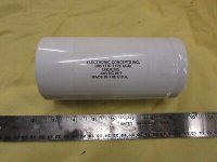
Just in case anyone was curious, and on topic, yes, you can get a 1000uF 400VDC film cap. Electronic Concepts makes large value Unlytic UL30 capacitors. It may be 3" diameter and 8" long, but they are available. I recently found some 1100uF ECI caps on Ebay.
Attachments
- Home
- Loudspeakers
- Multi-Way
- Replacing Standard Low Pass Xovers with Notch & Shelf Filters