I would like to replace the SMPS flyback supply with a linear power supply used in my Blu Ray player. I have tried improving on the existing SMPS flyback supply and I have had some successes – the noise is reduced as seen from the scope, and the sound is obviously improved, but ultimately could not completely get rid of the switching noise including ground noise. I could still see ripples and multiple ringing at the magnitude of up to 15mV ptp on the output lines and up to 5mV ptp noise on the ground at the switching frequency.
Thanks to the modular design, the SMPS power supply has its own board. It has the mains 110/230V input, and 12 connections on a socket. I think I could simply replace the board.
1. +5VSTB
2. PCON
3. +5V
4. +5V
5. GND
6. GND
7. +12VM
8. GND
9. +12VA
10. GND
11. -12VA
12. GND
I have no difficulties in designing some linear supplies for +5V, +12VM, +12VA and -12VA.
I have no issue in losing the STAND-BY function of the player if I have to.
I think +5VSTB can simply be connected to the +5V.
The question is, what about PCON? I presume I could use the same circuit as in the service manual which I own? But I am not 100% sure how that circuit works. If I don’t need the STAND-BY function, can I feed PCON from a resistor voltage divider from the +5V? If so, at what voltage?
And one more question, would I be able to easily find a 12 pin socket that matches the one in the player?
In my view, your generally clear questions lack some information for us to be able to help you.
Sounds like a good idea to replace the power board. A small problem - a linear supply (with transformer) is normally physically bigger than a corresponding SMPS.
If +5VSTB can be connected to +5V we cannot say for sure unless one of us has got a service manual as well. It sounds likely. Which blueRay DVD player are you talking about?
Just mentioning the abbreviation "PCON" give (most of) us even less idea about how it functions than you. If you tell which DVD player it is, perhaps there is a specialist with the service manual on the forum.
How does the 12pin socket look?
PCON is almost certainly a logic level control to put the SMPS in a low power state while preserving the 'all time' supplies such as +5STB (probably all time 5 volts for standby).
Measuring all the voltages in standby and on states will show which are all time rails and which are not.
Ultimately I'm not sure replacing the SMPS is a good idea... it is also very difficult to get accurate measurement of ripple and noise simply by clipping a scope probe to a rail because there are so many other factors influencing the result such as radiated pickup by the probe itself and problems with grounding and loops.
Thanks, guys. Mooly is spot on. The +5STB is the only all time on rail and it powers up the remote control which alters the PCON logic state to control if the other rails should be turned on or off, I guess. I didn't mention the brand name because I don't want to infringe copyright, as I may be able to copy a tiny portion of the schematic and post it here if I have to.
Agree that my measurements are inaccurate and at best they are indicative only. But I have modded the player many times during which time any reduction of noise reflected in the scope has always resulted in better sound. Now I have reached the stage that I can't reduce the noise further because the resonances probably came from physical limitations of pcb track lengths and components. I guess replacing it with linear supply is the only way to get rid of the switching noise altogether.
Getting rid of the switching supply means I can possibly lose the ability to put the player in standby mode. I don't mind that. I can keep the player rails on all time. I can switch the player off from the power board. So all I need to know is what to do with PCON.
If I follow Mooly's advice, I could measure the PCON voltage and set it to the voltage during the on state. But I don't know if it upsets the remote control circuit or not.
It all depends on how complicated you want to make things.
Adding FET/BJT rail switching would be easy to do for the switched rails, and all would then be controlled by PCON thus preserving the standby feature.
One possible issue with not having proper control over all rails is that the player might latch up if all rails appeared simultaneously at power on... you wouldn't know until you tried though.
If I follow Mooly's advice, I could measure the PCON voltage and set it to the voltage during the on state. But I don't know if it upsets the remote control circuit or not.
PCON is an input signal to the power supply, and its only function is to enable all the rails when you turn the player on.
Its function may be integrated with other requirements. For instance pressing OFF during playback almost certainly doesn't just kill the rails. The player will probably initiate a stop command first and then a few moments later activate the PCON line to actually turn the player off.
Mooly, you are right. I have just spent a bit more time studying the schematic and found that the job is a bit more involving than I like. I would need to copy a fairly large section of the circuits into the new linear supply in order to preserve the stand-by and slow turn-on, turn off sequencing features of blu ray player. There is too much work to my liking to head this path.
I will go ahead to do it only if I am able to set the PCON = 2V (On state) from the +5V supply so that all the rails are set to On permanently. The trouble is, there is no longer any Wait state so all rails will be turned on at the same time and turned off at the same time. I don't know if that will have any adverse effect.
Obviously, I cannot press the Off button while the disc is still spinning. The Off button will probably not work anymore. When I want to turn the player off, I will need to stop the disks from spinning, then switch the player off from the external power board / wall socket.
What I don't know is that if that will have a problem or not.
😕😕
Last edited:
Mooly,
Many thanks to you for your help and guidance. After considering your advice from the other thread, I went ahead modifying the player and changed it from Class II to Class I in order to allow further suppression of common mode noise. This improved the sound of the player.
Below are some pictures.
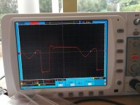
1. The wave form before upgrade.
2. The wave form after upgrade.
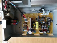
3. The upgraded board.
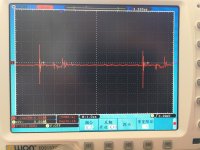
4. Ground noise after upgrade. It is still there but reduced.
Many thanks to you for your help and guidance. After considering your advice from the other thread, I went ahead modifying the player and changed it from Class II to Class I in order to allow further suppression of common mode noise. This improved the sound of the player.
Below are some pictures.
1. The wave form before upgrade.
2. The wave form after upgrade.
3. The upgraded board.
4. Ground noise after upgrade. It is still there but reduced.
Attachments

My guess is that PCON is 0V when the player is turned off. Then only the 5V standby rail is on, which powers up the remote control command board. All other rails are turned off. When I turn the player on by pressing the On button on the player or on the remote control, the remote control command board sets the PCON to 2V, which then activates all other rails. Of course, it is only my guess after spending limited time on the service manual.
I have just spent some time studying the service manual and the schematic.
I think that the player's CONTROLLER is powered by the +5VSTB standby rail all the time. When the player's ON button is pressed, it may first do a number of things then change PCON from 0V to 2V. The 2V on PCON opens a NPN transistor which turns on the +5V rail. At the +5V rail output, a voltage divider provides 1.6V to the base of a NPN transistor which turns on the +12V rail. Then a zener and resistor combination at the +12V output turns on another NPN resistor which turns on the -12V rail.
So basically, all rails other than the +5VSTB are turned on at the same time (or in sequence with a very small latency).
When the player is turned off, obviously the CONTROLLER does a number of things first then changes PCON from 2V to 0V. This turns off the +5V rail first. When the +5V rail output capacitor is discharged, the +12V rail will then be turned off, after which, when the +12V rail output capacitor is discharged, the -12V rail will be turned off. There is also a small latency between these steps.
I read the service manual of another DVD player with linear supply. I found that there are Relays to delay the turn on for the +/-12V and +8V (digital) supply but the CONTROLLER is powered on first.
I don't know how important to introduce delay of powers between the CONTROLLER and the other rails.
Its difficult to give exact answers without seeing how its all configured, however adding rail switching to a linear supply should be fairly easy using small power transistors as switches. They are either on or off and so would not require heatsinking.
The uProcessor PCON command will probably be a 0/5 logic level at the chip.
You can use a dual beam scope to check the switching arrangement and seeing if there is any delay in how the rails behave vs the PCON command… I suspect there won't be tbh, the rails will just turn on and off relative to the applied input.
All the sequencing will be done by the uP and associated servo chip.
Also, is there a negative -25 volt or so rail for the display ? If so, then that will normally be tied to the other rails via an arrangement of zeners etc to partially float the rail and so provide the correct operating conditions for the display... assuming it uses a vacuum fluorescent type... it may not of course.
the solution on sony dvp is....before power on connect pcon with gnd, after ~1-2sek disconnect pcon from gnd. better with one relais.
Maybe you could add filtering to the power supply to filter out switching noises, or resize existing chokes / capacitors.
How did the sound improve when altering the player from class II to I?
How did the sound improve when altering the player from class II to I?
You can use a dual beam scope to check the switching arrangement and seeing if there is any delay in how the rails behave vs the PCON command… I suspect there won't be tbh, the rails will just turn on and off relative to the applied input.
Good idea. I will do that when I get a moment.
Also, is there a negative -25 volt or so rail for the display ? If so, then that will normally be tied to the other rails via an arrangement of zeners etc to partially float the rail and so provide the correct operating conditions for the display... assuming it uses a vacuum fluorescent type... it may not of course.
There is a -12V rail for the DAC board. It is tied to the +12V rail via an arrangement of zeners, etc. as you described. But it is not connected to the display board. Only the 5V Standby rail is connected to the Display board.
the solution on sony dvp is....before power on connect pcon with gnd, after ~1-2sek disconnect pcon from gnd. better with one relais.
I don't understand why a delay of the rails is necessary when the player is turned on. For a player with Standby mode, it is necessary. But if I don't need the Standby mode, is it necessary? That is really the question I have.
I would hesitate to design a linear power supply board with full features supporting the Standby mode, as provided by the current SMPS board. I would much prefer designing a linear power supply board with quiet rails all turned on (or off) at the same time, without relays, and forget about PCON - just have PCON disconnected, to make the job much easier.
But would it work? without enforcing certain sequence or delay of the turn on of the rails, would the CONTROLLER locks itself up or produce some transient / THUMPs at the output or something that can damage the player?
Maybe you could add filtering to the power supply to filter out switching noises, or resize existing chokes / capacitors.
I have done those. In my opinion, the most important thing to do is to install RC snubbers. All RC snubbers on the secondary side are soldered under the PCB so you don't see them from the photo I posted. You can see 3 tall RC snubbers I installed on top of the PCB on the primary side. I retained the 10pF capacitor between the drain and source of the switching MOSFET, and has a new 2 x 470R + 100pF snubber on the MOSFET. 200pF was better but the dissipation was very high and the resistors (rated 6W) ran at temperature of 110 degrees. So I reduced it to 100pF and they are now at 85 degrees. I also have another one on the RCD diode, and on C. Because of these RC snubbers the switching wave form becomes substantially improved, having dU/dt reduced, and the major resonances damped, as you can see from the photos I posted.
I also improved the secondary side LCR filtering theoretically over 75dB or something modelled on LTSpice on each rail, and I used premium parts. However, I doubt in reality the result is as good as modelled. It does reduce the noise by some margin, but I don't trust my measurements because I didn't do them seriously.
Then I found / believed that the noise filtering only does so much, because I could have filtered out most differential noise, but none of these heavy LCR filters work to reduce the common mode noise! with an existing PCB, I have no way to install CM chokes on the secondary side. So I started the other thread asking questions about changing the player from Class II into Class I so that I can install a much higher value Y cap to reduce the common mode noise.
How did the sound improve when altering the player from class II to I?
I believe that the sound became cleaner and more detailed. But this is subjective. More importantly, even with improper measurements I found the ground noise was reduced. This is objective. Changing from class II to class I allows a larger Y cap that is responsible for reducing the common mode noise. The Y cap in the original player was 470pF. I have now increased it to 4700pF. This is very well within the spec of Class I. Class II wouldn't allow that.
Smps to improved smps
How is modded power supply now? I happened to have the exact smps as yours. And I would like to improve it.
How is modded power supply now? I happened to have the exact smps as yours. And I would like to improve it.
- Home
- Amplifiers
- Power Supplies
- Replacing SMPS with Linear Supply on Blu Ray player