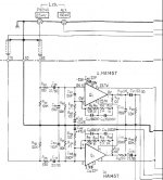
A power supply failure led to the destruction of these HA1457 devices in the phono stage. These are 8-pin SIP single channel opamps, and I plan on manufacturing a small adapter board and replacing the singles with one double opamp (yes, I plan on dropping the supply voltage a bit).
How would the NE5532 do as a 'drop-in' replacement here? I'd like to keep the other component values for simplicity and cost...this is not a world-beater preamp, but certainly I'd like the best component I can use within a reasonable price (anything over $5 or $6 per-opamp is too much for this project).
Thanks!!
Attachments
Hi,
you could also try an OPA2604. It´s a lot more expensive than an NE5532 but stil way under 5$.
I think this OP is very good value for money.
william
you could also try an OPA2604. It´s a lot more expensive than an NE5532 but stil way under 5$.
I think this OP is very good value for money.
william
phono amp
Why not a simple and cheap TL072? And when busy leave out the in- and output capacitors. There's more music without them and who cares about a few millivolts offset?
John
Why not a simple and cheap TL072? And when busy leave out the in- and output capacitors. There's more music without them and who cares about a few millivolts offset?
John
Hello Echowars,
You may wish to check out a post on the FMtuners yahoo group from July of this year:
http://groups.yahoo.com/group/FMtuners/message/9667
The HA1457 is used in the audio output stages of some tuners such as the Kenwood KT-815. Bill Ammons makes a converter PCB that mounts in place of the HA1457 and converts it to a standard 8 pin DIP socket so that you can try out any number of opamps. Whether it is easier than making your own, I'm not sure.
I have not used this PCB, but I have bought IF filters and his IF Filter adder boards. He seems very good to deal with.
Steve.
you could also try an OPA2604. It´s a lot more expensive than an NE5532 but stil way under 5$.
I am a fan of the 2604...it's a great part. I also like the TL072 for inexpensive applications. But for a phono input stage, the 2604 has twice the input noise of the 5532, and the 072 noise is three times the 5532. You all still think the noise of these parts is low enough for a phono stage?Why not a simple and cheap TL072?
spind...
I may have to check this out. Thanks for the tip.
OPA2132 and OPA2134 both have just marginally higher voltage
noise than NE5532 and are FET input, so current noise
shouldn't be a problem.
noise than NE5532 and are FET input, so current noise
shouldn't be a problem.
OPA2134 looks like a real possibility...wonder why I overlooked it?
Could I toss the caps on the inverting and non-inverting inputs, and the output? Or should they stay...?
Could I toss the caps on the inverting and non-inverting inputs, and the output? Or should they stay...?
JoeBob said:You could use two AD797s, it's rather low noise. Although I don't know how much these cost 🙁
It is very low noise, but also
Very expensive, considering the proposed budget. Needs a
converter too, since it is a single op. LT1115 is a bit cheaper
and almost as good in noise, but still only a single op and
also well above the budget.
EchoWars said:OPA2134 looks like a real possibility...wonder why I overlooked it?
Could I toss the caps on the inverting and non-inverting inputs, and the output? Or should they stay...?
I seem to remember a discussion a while back that the input
offset voltage/current of opamps might be high enough to
be harmful to the cartridge. I might have got it wrong though.
The input caps should avoid this problom anyhow to be on
the safe side. It depends on the which opamp and which
cartridge too, of course.
Edit: just checked back on the schematic. I suppose one of
the caps you're referring to is the one tied directly between
the inputs. That ones most likely there for RFI surpressiona
and/or stability issus, so I strongly suggest keeping that one
too.
No, I can see that the one tied between the inputs if for EMI. Was wondering about the 2.2µf caps at the input and output, and the 470µf at the inverting input.
You may be correct that the ones at the non-inverting and inverting inputs should stay in place though...perhaps the one at the output can go if offset is low enough.
Regarding the AD797...I was considering it for another project, but I heard it was difficult to work with (stability). Might have to see for myself.
Nooo! No LT1115!
I strongly disrecommend the LT1115, LT1028 and AD797 for moving-magnet amplifiers. They have a very low voltage noise, but their current noise is way too high (especially with unmatched impedances driving the positive and negative inputs). An NE5532A or one of the modern low-noise FET op-amps should work fine.
For moving-coil, the LT1115, LT1028 and AD797 are some of the best op-amps on the market, but this circuit is clearly intended for moving magnets.
...yes it is, which is why it's getting a OPA2134. Been wanting to try one, now seems like the time.
op amps
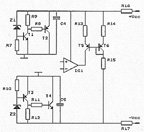
We designed a circuit with the AD797 which is used in our surround pre-amplifier.
The 797 is a very low noise amplifier AND it's for the major part of it a CURRENT amplifier! It also warms up adding some 20 degrees C to the room temperature.
What we first do now with op amps is using a "shunt regulator" to isolate the circuit from the mains power supply. The circuit is further "warmed up" with an extra 30 degrees by the current mirror at the output.
Results are amazing. This could be done with any op amp only beware not to draw too much current from the output.
Attachments
The cap between + and - inputs is a typical japanese RFI thing. Remove both input coupling cap and this cap. Even the output cap is unnecessary unless you want to have a "mild" rumble filter.
You can (or should) remove the 680 ohms resistor at the input. This is a part of the RFI filter. If you HAVE trouble with RFI do use these filter otherwise they add nothing to the sound quality, on the contrary.
You can (or should) remove the 680 ohms resistor at the input. This is a part of the RFI filter. If you HAVE trouble with RFI do use these filter otherwise they add nothing to the sound quality, on the contrary.
Interesting argument Per.peranders said:..snip..
If you HAVE trouble with RFI do use these filter otherwise they add nothing to the sound quality, on the contrary.
What abour the counter-argument that low level RF interference may harm the sound quality 😉
peranders said:The cap between + and - inputs is a typical japanese RFI thing. Remove both input coupling cap and this cap. Even the output cap is unnecessary unless you want to have a "mild" rumble filter.
You can (or should) remove the 680 ohms resistor at the input. This is a part of the RFI filter. If you HAVE trouble with RFI do use these filter otherwise they add nothing to the sound quality, on the contrary.
This is not a good advice unless the components are of inferior quality. The input is filtered at 1.5 MHz and the output filter at around 95 kHz. The capacitors (100 pF and 3300 pF) should not be ceramic ones. Ceramic capacitors vary their value with the amplitude of the signal. So use polyester or (better) polystyrene ones. If those are not available use 1 NF (1000 pF) at the input, the cut off frequency then becomes 150 kHz.
If you read the manufacturer's application notes you'll find the reasons that it has to be tended too a little carefully -- it's not a "plug and play" chip but I wouldn't be dissuaded from using it just because someone didn't compensate it correctly.EchoWars said:Regarding the AD797...I was considering it for another project, but I heard it was difficult to work with (stability). Might have to see for myself.
All is revealed in ADI's PDF on the '797
Another thing with the AD797, if I remember correctly, is that
in order to improve the noise performance, there is no emitter
degenration on the input diff pair. That means it is easier to
overload the input and get outside the (almost) linear region.
Hence, these ops are mainly suitable for very low level
applications, and not a general replacement for other op
amps.
Well, I believe the RFI filter will have to stay. Once I get this up and running it is being shipped across the country to its new owner. If he has problems with RFI, I get to foot the bill to ship it back, fix it, and return it to him. So in this case I'd rather be safe than broke. 
So, the 2.2µf at the input, the 470µf at the inverting input, and the 2.2µf at the output can all go...since I'm using a J-Fet opamp and input currents are very low..?? Correct?
So, the 2.2µf at the input, the 470µf at the inverting input, and the 2.2µf at the output can all go...since I'm using a J-Fet opamp and input currents are very low..?? Correct?
- Home
- Source & Line
- Analogue Source
- Replacing Dead Phono Opamp...What to Use??