If you have set your DMM to diode test mode, your measurements indicate taht all these transistors are faulty. In this case I'd check the remaining ones also.
I also did not get if you listed just the ones that tested faulty or just the ones you took out?
But as you have decided to change them all, which is certainly the best idea, it won't matter.
Last edited:
So I replaced all transistors, found 2x that were faulty (including one of the outputs). I also checked the resistors in that area and replaced R20 (it was open). Any advice on next steps before slowly bringing up the voltage with a variac and bulb limiter?
I'll bite. (PRR , Gno and George must be busy elsewhere).
First, if you can power up everything EXCEPT the output stage, do so and check that's all good.
Second, fast blow fuses in your power rails to the output devices is a good idea.
Then check that your DC voltages (and temperatures) are good before trying to apply any signal or load
First, if you can power up everything EXCEPT the output stage, do so and check that's all good.
Second, fast blow fuses in your power rails to the output devices is a good idea.
Then check that your DC voltages (and temperatures) are good before trying to apply any signal or load
How would I power up everything except the output stage? A bunch of power supplies? If so, I unfortunately don't have access to any...
Where are these fast blow fuses located? Are they something I'd have to install myself?
Where are these fast blow fuses located? Are they something I'd have to install myself?
I usually disconnect the collectors or leave the power devices out until I've tested the rest of the circuit. Sometimes you can't easily do that and/or it messes with the FB loop too much.
Fuses just go in series with the power connections. Make them much smaller than needed for full power while you check that nothing is awry. Really only need to support the standing bias current plus a bit more to charge up some capacitors.
Fuses just go in series with the power connections. Make them much smaller than needed for full power while you check that nothing is awry. Really only need to support the standing bias current plus a bit more to charge up some capacitors.
So I reinstalled the power amp board, disconnected the preamp board, and began powering up (variac >> bulb limiter >> amp, no speaker connected). The bulb began to glow around 4 VAC (measured on the power transformer primary), so I quickly powered down. I checked the PT resistances, they measured ~1.5 ohms across the primary (1-2), .5 ohms between 3 and 4, .5 ohms between 4 and 5, and .9 ohms between 3 and 5. There was no continuity between the primary and the secondary windings.
What do you all recommend as my next step? Should I disconnect the PT and check its voltage at full 120VAC input?
What do you all recommend as my next step? Should I disconnect the PT and check its voltage at full 120VAC input?
Should I disconnect the PT and check its voltage at full 120VAC input?
Yup, with the bulb in series.
Looks like you need to start from the input and find out what's drawing so much current.
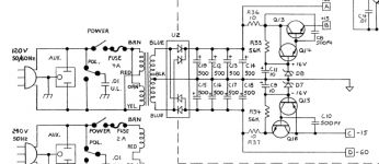
Applying ~120VAC to the primary of the power transformer (with secondary disconnected) yields ~41 VAC across 3-4 and 4-5 of the secondary, and ~81 VAC across 3-5 of the secondary. Are these values expected? If so, what should I check next? The schematic shows +/- 60 VDC from the rectifier (U2), does that correspond to +/- 80VAC input?
It's possible the glow in the bulb I saw previously was normal (and I chickened out). Should I expect glow in the bulb at input voltages as low as 4AC?
It's possible the glow in the bulb I saw previously was normal (and I chickened out). Should I expect glow in the bulb at input voltages as low as 4AC?
Applying ~120VAC to the primary of the power transformer (with secondary disconnected) yields ~41 VAC across 3-4 and 4-5 of the secondary, and ~81 VAC across 3-5 of the secondary. Are these values expected? If so, what should I check next? The schematic shows +/- 60 VDC from the rectifier (U2), does that correspond to +/- 80VAC input?
Ok, so 80VAC center tapped (that is, +/- 40VAC) will give roughly +/- 60 VDC.
That is, the center tap needs to be tied to earth and the two outside taps sent to a pair of diodes, one for each of the rails.
If you're rectifying 80VAC you're going to get +/- 120VDC. Which you don't want.
It should look like this
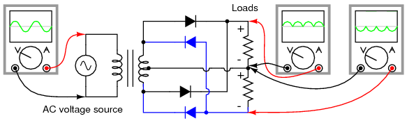
(from All about circuits)
If your bulb is glowing brightly you're pulling mains current. It's got to be going somewhere. It is possible, given the age of the amp, that one of the filter capacitors has started leaking badly. Off the top of my head I can't recall what the formula for acceptable leakage is (Anyone? Ferris?) but you put a resistor in series with the cap and measure the voltage ratio (12VDC will do for starters). Be aware that the cap will appear as a dead short on start up so your resistor needs have enough wattage for this.
Conrad Hoffman (who's sometimes hereabouts) wrote a short article on this topic
Last edited:
As a note: the bulb did not glow brightly at 4 VAC on the variac, but more than I thought it should have.
A 120V bulb can't glow at ALL with 4V from the Variac.
So you have something wrong, but we can't know what.
So you have something wrong, but we can't know what.
Is it safe to connect the secondaries of the transformer one at a time until the bulb begins to glow? That might help isolate the issue.
Thought I'd posted this earlier.
Better to first disconnect the secondaries individually; disconnect and check the PSU electros. Then check secondaries with rectifiers and electros ONLY.
That will at least establish if your power supply is OK.
Better to first disconnect the secondaries individually; disconnect and check the PSU electros. Then check secondaries with rectifiers and electros ONLY.
That will at least establish if your power supply is OK.
Before power transformer is like rectifier cricuits:
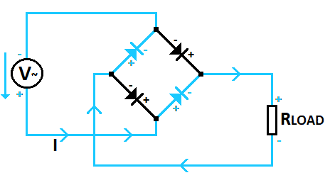
from How does Rectifier Diode work? - Definition and conctruction
This is Full-Wave Bridge Rectifier circuit (alternating current, reverse bias)
from How does Rectifier Diode work? - Definition and conctruction
This is Full-Wave Bridge Rectifier circuit (alternating current, reverse bias)
I'll pipe up and fess up - I also now own a burnt RB400. Mine has been repaired but is oscillating at c. 100kHz (and yes, the IMD is audible - which is how I discovered the oscillation). First set of measurements are weird so I need to recheck them (I recorded signals on N/C pins on the op amp).
- Home
- Live Sound
- Instruments and Amps
- Replacing Burnt Components on Gallien Krueger RB400 Bass Amp