The pins of the zenors... Personally the inductance of PTH caps will not help, a small low parasitic inductance SMD device would be better.
Even though this is done as common practice the gains are often very very small, so small in fact they are probably only noticable where a zenore is used as a precision voltage reference and even here there are better devices now available. But it dosn't do any harm, but large PTH caps are NO GOOD for decoupling due to the addition of parasitic inductance. The noise being decoupled is usually higher frequency so needs the low inductance caps to work at the required frequencies.
COG class 1 ceramics are an excellent choice.
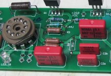
+1 ! I stock many values of MKP10. However they sometimes are simply too large.
To conclude I will go to my stock NOW and check if I have 470 nF MKP in 10 mm.
To conclude I will go to my stock NOW and check if I have 470 nF MKP in 10 mm.
+1 ! I stock many values of MKP10. However they sometimes are simply too large.
To conclude I will go to my stock NOW and check if I have 470 nF MKP in 10 mm.
I recommend MKP-2-63V (10nf-1uF) with 5mm footprint. Best German quality.
Hi that is a good tip ! I never used MKP2. I see there is a 470 nF 100V in 5 mm pitch. Using a somewhat smaller cap should not be a problem as, according datasheet, lead wires are 6 mm each. It seems some PCB revisions of the 909 have an extra solder pad for smaller caps so that would be splendid.
OP can do his homework himself:
http://www.wima.com/EN/WIMA_MKP_2.pdf
Checked my stock and I have 470 nF MKP 100V in 10 mm but not Wima....
OP can do his homework himself:
http://www.wima.com/EN/WIMA_MKP_2.pdf
Checked my stock and I have 470 nF MKP 100V in 10 mm but not Wima....
Last edited:
Jean-paul,
With the first link you provided, the EPCOS/TDK is; 47 uF, DC 450, AC 160. Is this ok to use in the Quad?
Also can you possibly describe the sound of polypropylene compared to MKT?
: )
With the first link you provided, the EPCOS/TDK is; 47 uF, DC 450, AC 160. Is this ok to use in the Quad?
Also can you possibly describe the sound of polypropylene compared to MKT?
: )
It is a 0.47 uF cap so yes but maybe the others are smaller. That is your homework. First measure the size of the old ones and make a choice. The Wima MKP2 seems a good candidate too. This is my last comment as I could have replaced many caps in the meantime.
Don't fear evil, take the challenge ! Overcome your own barriers and jump in the deep. The immense joy of replacing 2 caps and go where no man has gone before you 🙂
Don't fear evil, take the challenge ! Overcome your own barriers and jump in the deep. The immense joy of replacing 2 caps and go where no man has gone before you 🙂
Last edited:
Think global, act local 🙂
This is the future and the past "tend your own garden". 😀
Please don't mess up "religion" with "science" and "evidence"! Thank you.
Best regards!
It is not so much religion as a misleading statement. Nobody ever says 'all coupling caps sound the same' but it is an 'alternative fact' as it would be called these days used to shore up one's own view. Which may or may not be based on anything substantial.
Jan
Is "C2" a coupling capacitor? Then it won't "sound" at all. Dielectric in recent film capacitors is irrelevant in terms of sound qualitiy, unless there is significant AC level across the cap, which in a properly sized coupling cap isn't.
Best regards!
Capacitors do not have a sound. Capacitors in circuits may have a sound, especially if the circuit is poorly designed. There is no such thing as a 'good' cap; there are good caps for particular uses in particular circuits, the same cap used for another purpose in another circuit may be quite bad.
I agree wholeheartedly. To get more specific, the "design" aspects can be enumerated pretty easily. The basic linear parameters of a capacitor are its bulk capacitance, its effective series resistance, and its self resonant frequency, which is just a simple way of lumping together the important inductances to get a magic frequency, below which, the capacitor behaves like a capacitor, and above which, the capacitor behaves like an inductor.
Those basic parameters can be put into the context of a circuit, and can describe much of the behavior of that cap in a circuit. For example, if a cap is used to filter out high frequencies, then the bulk capacitance will tell you how much capacitance the part will offer, and thus how much 'filtering' action it can provide. The self resonant frequency will tell you the maximum frequency that the cap will behave like that bulk capacitor, and the effective series resistance (ESR) will tell you how much real loss the capacitor will provide. This is important since, near the resonant frequency, the bulk of the capacitor's impedance will be its real loss, roughly equal to the ESR. For some filters, the ESR determines the residual output of the filter, and not the bulk capacitance, so its magnitude, as well as the self resonant frequency of the part as a whole, are both important.
There are higher order characteristics, such as the various nonlinearities due to the type of dielectric and the quality of the electrode connections, but the great bulk of a cap's behavior is defined by the basic linear parameters listed above.
So, while it's attractive to jump straight to the high order behavior of a capacitor in order to select an 'ideal' part, the basic linear behavior of a cap will have the dominant effect, and this needs to be considered in the context of the circuit to which it is applied. A cap with a "better" dielectric that has insufficient bulk capacitance or too low of a self-resonant frequency should sound "worse", because the basic circuit requirements aren't being addressed properly.
After that, there is also the possibility of using a combination of several caps to achieve the required performance, but still, we're talking about the basic linear behavior of these caps in combination, and the high order effects are still often far less important than the basic capacitance, ESR and self-resonant frequency of each of the parts, as they are connected together in a circuit.
A suggestion is to focus on the basic engineering of the circuit relative to the basic properties of the capacitor. Simulations are quite wonderful for this, since they allow an engineer to lash up a circuit using models of 'real' capacitors that have a defined self resonance, and a defined ESR. While constructing a prototype is most valid, a carefully crafted model can often get a designer 90% of the way to the actual performance of a part in a circuit. Further, many vendors provide fairly detailed SPICE models for their capacitors, and these can be used to study and verify the behavior of a proposed circuit without having to purchase parts, wire them up, and measure them.
So yes, "capacitor sound" should not be confused with the basic suitability and performance of a cap in a given circuit - that kind of basic engineering can be done with equations or simulations, and really does need to be done before these ephemeral high order effects should even be considered. Many of the "great" circuits that are so often emulated today became "great" because they addressed the functional requirements of the circuit, given the real behavior of the parts available.
Build the 'nuts and bolts' of a circuit first, and then later perhaps worry about the paint job.
I have compared Nichicon UKZ, UKA and KZ and Panasonic FC, FM and FR.
And my favorite is…..Panasonic FR!
For some time I settled on Nichicon KZ until I tried Panasonic FM. I loved that capacitor until I tried the even better sounding Panasonic FR capacitors.
I have tried Elna RE3, Nichicon FW, Nichocon KZ, Panasonic FM, FC, FR, NHG, AM (for audio). I have the same feeling, the FR did appear best of all. The "for audio" thing seems to denote capacitors with lower ripple current and usually 85C electrolyte, both considered inferior characteristics. The new FR is really very good, I have it as output cap in my headphone amp too and have no complaints at all. Maybe 15 years ago the "gold" series Nichicons were superior but today there`s a lot more competition and in my opinion - better ones.
Basi says SMR sounds better than polypropylene, anyone else agree?
I would love to hear more opinions.
I would love to hear more opinions.
Buy some Smr,some Mkp different manufactures.Listen experiment then judge by yourself.Basi says SMR sounds better than polypropylene, anyone else agree?
I would love to hear more opinions.
It's all up too u in the End!!!
I would like to hear an opinion on how a correctly-calculated coupling cap (so it has little signal voltage across it) with any reasonable dielectric (so fairly linear) can possibly affect the signal to an audible extent. Such an opinion would need to explain either how a normally well-behaved cap somehow behaves completely differently when asked to convey a music signal, or how a simple potential divider can somehow escape from the restraints of Kirchoff's voltage law.Sonic77 said:I would love to hear more opinions.
I agree with you Mario.
On paper Panasonic FM and FR have the exact same specifications. The datasheets are identical. So, because I already loved the FM’s it took quite a while until I tried the FR’s. Also I did not expect to hear any differences. Nevertheless, without doubt, the FR’s sound better!
On paper Panasonic FM and FR have the exact same specifications. The datasheets are identical. So, because I already loved the FM’s it took quite a while until I tried the FR’s. Also I did not expect to hear any differences. Nevertheless, without doubt, the FR’s sound better!
Provided the 330nF is only operating as a DC blocking and AC coupling capacitor.
If instead it is operating as a filter, then the AC voltage across it does bring parameter variation into the comparison equation.
If instead it is operating as a filter, then the AC voltage across it does bring parameter variation into the comparison equation.
Maybe you guys like a "soft" and "boring" sound? Nothing wrong with that but it's not for me. Here are some quotes i found on the internet regarding Panasonic caps lol;
“Panasonic FM’s tend to be overly smooth and tubby and a little slow".
“If you can, use Elna Silmic II instead of Panasonic FM”.
“In the signal path I would take BG or Silmic II rather than Panasonic FM".
“Panasonic FC’s are rolled off in the highs and also the lowest octave, they have a 2D sound”.
“All low impedance capacitors such Panasonic FC/FM Elna RJH etc sound bad with improper tonal balance and sound dirty when compared to Nichicon KZ, FG, BG FK NX, Elna Cerafine, Silmic II, Silmic”.
“Panasonic FC sounds really flat (2D) and closed in. The Silmic, Cerafine, Nichicon KZ, and ES are better by a large and noticable margin. Panasonic FC are a general purpose cap, and when put up against the other contenders (audio grade) they just don’t hold up.”
“I have used Panasonic, Elna and Nichicon. In my opinion stick with Nichicon, they sound good and are very reliable. But it all depends on what sound you like, Nichicons are snappy and precise, and Panasonics are mellow, more like tubes”.
“Nichicon KZ/FG are very analytical and clean sounding. Unlike Panasonic FC, the Nichicons don’t have any high frequency roll off, they image well and they go all the way down in the bass”.
Last edited:
I would like to hear an opinion on how a correctly-calculated coupling cap (so it has little signal voltage across it) with any reasonable dielectric (so fairly linear) can possibly affect the signal to an audible extent. Such an opinion would need to explain either how a normally well-behaved cap somehow behaves completely differently when asked to convey a music signal, or how a simple potential divider can somehow escape from the restraints of Kirchoff's voltage law.
Measurement is the king. Not listening.
Yes, although even then most film cap types are OK.Sonic77 said:If instead it is operating as a filter, then the AC voltage across it does bring parameter variation into the comparison equation.
Listening tells us what to measure.diyralf said:Measurement is the king. Not listening.
- Home
- Amplifiers
- Solid State
- Replacement Parts for Quad 909