I built an amp for my sister using Icepower ASX50 modules (4 channel) and after a short time one of the modules went up in smoke so I replaced it with another one I had as I assumed it would be something I couldn't fix.
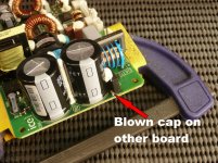
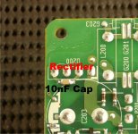
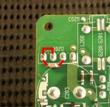
I have had a play with the broken module today and realised it has just blown a small cap on top of the board that is across two pins of the rectifier, see picture. There is another cap on the bottom of the board (see picture) that is also across two pins of the rectifier, I removed that cap & measured it and it is 10nf. I have a couple of questions I'm hoping somebody can answer.
I have had a play with the broken module today and realised it has just blown a small cap on top of the board that is across two pins of the rectifier, see picture. There is another cap on the bottom of the board (see picture) that is also across two pins of the rectifier, I removed that cap & measured it and it is 10nf. I have a couple of questions I'm hoping somebody can answer.
- Given I have 250V in my house do I have to use a replacement cap with a voltage higher than 250v?
- I will not be able to solder the cap back into the original position so I was thinking of using a leaded cap & soldering it across the rectifier pins under the board, would this be ok?
- What does this cap do?
Attachments
You will be wise to remove the damaged capacitor and fit a new one in the same position. Use the correct voltage, temperature and value for reliability and most importantly, safety!
On close inspection I would replace both as they are used to balance the power switching components.
On close inspection I would replace both as they are used to balance the power switching components.
Just so there's no confusion the module in the photos is fine, the damaged module is fixed to a board so it was easier to take photo's of a module I had laying around.
When you say "use the correct voltage" what does that actually mean? The choices in leaded ceramic cap at the local supplier are, 50v, 100v, 200v & 500v, I assume I should use the 500v?
When you say "use the correct voltage" what does that actually mean? The choices in leaded ceramic cap at the local supplier are, 50v, 100v, 200v & 500v, I assume I should use the 500v?
Which pins of the bridge is each cap across ? The caps could see much higher than 500 volts across them.
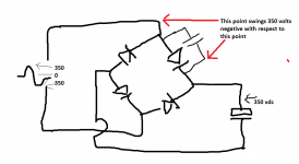
When the mains is at its peak (250 vrms is over 350 volts peak) then the + terminal of the bridge is at around 350 volts DC. As the mains swings toward the negative half cycle then the AC input pins swing 350 volts (peak) below that voltage. So the cap could see 700 volts peak across its terminals.
Caps for this kind of duty are normally specified as such (not standard 1000 vdc caps)
This might help. The cap is shown across one diode, I've used AC to bridge positive because its easier to visualise but its exactly the same from AC to negative. The cap can see 700 volts each half cycle. That means a 1000 volt DC rated part is needed but nowadays parts for mains duty are always rated as such. A standard 1000 volt part might not survive because its a 'tough' location with frequent mains spikes and so on easily exceeding the rating.
Attachments
This might help. The cap is shown across one diode, I've used AC to bridge positive because its easier to visualise but its exactly the same from AC to negative. The cap can see 700 volts each half cycle. That means a 1000 volt DC rated part is needed but nowadays parts for mains duty are always rated as such. A standard 1000 volt part might not survive because its a 'tough' location with frequent mains spikes and so on easily exceeding the rating.
Don't you hate that, I jumped in and ordered 500v caps before your first post🙄they had 1000V as well🙁
Lol, it happens.
Even a standard 1000 vdc rated part might not be enough though. The function of these caps is to stop interference getting out of the PSU as much as anything else (and to pass EMI regulations and so on).
Even a standard 1000 vdc rated part might not be enough though. The function of these caps is to stop interference getting out of the PSU as much as anything else (and to pass EMI regulations and so on).
So what cap would you recommend, they just look like tiny boring old SMD ceramic caps.
Last edited:
They are anything but (or should be).
Caps for mains duty need to be specially selected. Something similar to these Vishays would be suitable.
These are 250vac rated and are designed for this kind of use. The other file tells you when and where to use Class X and Class Y ratings and what the risks are.
Caps for mains duty need to be specially selected. Something similar to these Vishays would be suitable.
These are 250vac rated and are designed for this kind of use. The other file tells you when and where to use Class X and Class Y ratings and what the risks are.
Attachments
They are anything but (or should be).
Caps for mains duty need to be specially selected. Something similar to these Vishays would be suitable.
These are 250vac rated and are designed for this kind of use. The other file tells you when and where to use Class X and Class Y ratings and what the risks are.
Thanks, so something like this in a leaded cap DE2F3KY103MA3BM02 - MURATA - CAP, CER, F, 10NF, 250V, RAD | element14 Australia
Ive got some of thesehttp://au.element14.com/vishay-roederstein/mkp1840310104m/product-range-mkp1840m-series/dp/1413881?ost=mkp1840310, there good for 1000VDC & 500VAC 🙂 bit big though 🙂
Maybe the Kapoof was caused by B&O skimping on the caps🙂
Maybe the Kapoof was caused by B&O skimping on the caps🙂
The PIV (peak inverse voltage) rating of a bridge rectifier should be at least 3times the AC voltage applied across the bridge rectifier.
i.e. for a 240Vac transformer winding or supply, the bridge rectifier should be rated to at least 720V
This is for the whole bridge rectifier.
For a discrete 4 diode rectifier, each diode must be rated for half that, i.e. for a 240Vac winding/supply use >360V diodes.
In the UK the maximum supply voltage (not including interference) is now 253Vac. Prior to harmonisation it was 254Vac.
The new harmonised supply would require the bridge rectifier to have a PIV rating of > ~759V
Does this apply over the whole of Europe?
Last edited:
Mooly can you look again?This might help. The cap is shown across one diode, I've used AC to bridge positive because its easier to visualise but its exactly the same from AC to negative. The cap can see 700 volts each half cycle. That means a 1000 volt DC rated part is needed but nowadays parts for mains duty are always rated as such. A standard 1000 volt part might not survive because its a 'tough' location with frequent mains spikes and so on easily exceeding the rating.
I think you have two diodes in series resisting the 700Vpk reverse voltage.
Thanks, so something like this in a leaded cap DE2F3KY103MA3BM02 - MURATA - CAP, CER, F, 10NF, 250V, RAD | element14 Australia
They look OK
Andrew... I'm not following you. The photo shows what seems to be a standard mains input to an SMPS. L and N via a choke and applied to the bridge.
you point to 700Vdc (post6) across the capacitor and diode.
But as I see it there are two diodes in series resisting that 700Vdc.
Each diode sees ~ half peak inverse voltage if they both leak the same current.
Or do I see it wrongly?
But as I see it there are two diodes in series resisting that 700Vdc.
Each diode sees ~ half peak inverse voltage if they both leak the same current.
Or do I see it wrongly?
More usually no choke and via a current limiting Power NTC.L and N via a choke and applied to the bridge.
Last edited:
Any thoughts on my cap choice, post 11 🙂
Well, just that they look OK electrically. You're aware they are much larger physically than those fitted originally.
Yes but smaller than the ones I have 🙂
I cannot solder back into where the blown cap was so it will be easier to solder directly to the rectifier pins & an smd may not be so good for that.
I cannot solder back into where the blown cap was so it will be easier to solder directly to the rectifier pins & an smd may not be so good for that.
The PIV (peak inverse voltage) rating of a bridge rectifier should be at least 3times the AC voltage applied across the bridge rectifier.
i.e. for a 240Vac transformer winding or supply, the bridge rectifier should be rated to at least 720V
This is for the whole bridge rectifier.
No, each diode of the bridge has to block one single peak voltage, as is stored in the bulk cap behind that rectifier. Thus the standard voltage of primary rectifiers found in ac adapters is 400Vac.
- Status
- Not open for further replies.
- Home
- Amplifiers
- Class D
- Replacement Capacitor Question