Well, the choice has already been made 🙂 . I don't see any point in picking at the device any further.You have to go with what you think works best

The purpose of C3 is to avoid the loss of feedback at super audible frequencies that might cause instabilities. It ~cancels the shunting effect of stay capacitance and the input capacitance of the op-amp. Its effect starts at 1k&330p => 482KHz and above.I will ask, perhaps, one more question: can the nominal value of C3 turn the phase?
It turns out that this is essentially an LPF?The purpose of C3 is to avoid the loss of feedback at super audible frequencies that might cause instabilities. It ~cancels the shunting effect of stay capacitance and the input capacitance of the op-amp. Its effect starts at 1k&330p => 482KHz and above.
More like maintains a flat response instead of a high frequency boost from the loss of high frequency feedback. The input capacitance of the op-amp does not appear as a component in the schematic, but all op-amps will have it. Loss of 500KHz in the signal path is no problem but it is a problem for the feedback path.
I got curious over this and started looking...
From:
https://electronics.stackexchange.c...e unity-gain followers with a resistor in the

My own view is that for audio and for a 'slow' opamp, well tbh I'm struggling to see why this is implemented. Is it something odd about the 4559 that needs this ? This is more a technique you see used used with CFB (current feedback) opamps.
From:
https://electronics.stackexchange.c...e unity-gain followers with a resistor in the
My own view is that for audio and for a 'slow' opamp, well tbh I'm struggling to see why this is implemented. Is it something odd about the 4559 that needs this ? This is more a technique you see used used with CFB (current feedback) opamps.
So, at that frequency C3 acts like a short circuit (a piece of wire) from output to input?The purpose of C3 is to avoid the loss of feedback at super audible frequencies that might cause instabilities. It ~cancels the shunting effect of stay capacitance and the input capacitance of the op-amp. Its effect starts at 1k&330p => 482KHz and above.
A good operational amplifier! But in my case, with this op-amp, for some reason there is an offset of +40 mV at the outputs on one channel and -45 mV on the other channel. I do not understand what this is connected with.NJM2114 opamp
The offset is normal for a circuit such as you show. DC precision is not accounted for in the design (and it doesn't make any real difference). The stages are all AC coupled to partly allow for that. The 100k +1k input bias resistors would need an equal value (101k) in place of R3 to keep the input offset bias voltages equal but that would be bad for the performance in other ways.
If you keep the 4559 then you could measure the voltages across the electrolytic coupling caps and fit them according to the polarity of voltage you measure. That might mean reversing some of them.
If you keep the 4559 then you could measure the voltages across the electrolytic coupling caps and fit them according to the polarity of voltage you measure. That might mean reversing some of them.
The NJM2114 uses NPN bipolar transistors for the input LTP, and the input bias current for these transistors is spec'd at typical 0.5 uA. That means that a 100K input resistor produces a 50mV drop. If the two inputs are fed by a matching resistors, then the input voltages cancel, but if they do not match then there will be an offset depending on which resistance is greater and the polarity of the BJT LTP transistors. An advantage of FET input op-amps is that the input currents are essentially zero so there is no need to match these resistors.
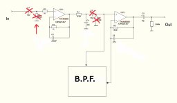
R2 is critical and the circuit will not work without it. It biases the input to zero volts DC. The difference now is that there is no bias current flowing out of the opamp inputs and into that resistor. That means no voltage is developed across the resistor and so no DC offset at the opamp output.
The value is not so critical now. Even a 10Meg will bias the opamp correctly and give no offset but a 100k is perfect here and it sets the input impedance seen by whatever you connect to the input.
You could short C2 and the first opamp output (which will have no DC offset) now correctly biases the second opamp input. R6 could now be removed. If you leave C2 in place then you must also leave R6 in place.
Yes, but there is already a 220 kOhm resistor directly at the input. Let me remind you that the electronic switchboard has been removed and a relay has been installed instead.100k is perfect here and it sets the input impedance seen by whatever you connect to the input.
Attachments
You must ensure that no opamp input is ever left floating. You asked about R2 in the diagram you posted 🙂 and it essential that resistor either remains or you must ensure that whatever is before that resistor ties the opamp input to ground at DC.
All inputs must be ground referenced and that is what all those resistors do.
All inputs must be ground referenced and that is what all those resistors do.
Thanks! A completely comprehensive answer.👍You must ensure that no opamp input is ever left floating. You asked about R2 in the diagram you posted 🙂 and it essential that resistor either remains or you must ensure that whatever is before that resistor ties the opamp input to ground at DC.
All inputs must be ground referenced and that is what all those resistors do.
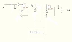
That should work fine as drawn.
Just be aware that not having an input coupling cap means the circuit can respond to and amplify any DC voltage that is applied to the input. Although the output coupling cap prevents any voltage being passed further on it is still good practice to AC couple inputs 🙂 Just sayin' 😉
Just be aware that not having an input coupling cap means the circuit can respond to and amplify any DC voltage that is applied to the input. Although the output coupling cap prevents any voltage being passed further on it is still good practice to AC couple inputs 🙂 Just sayin' 😉
- Home
- Source & Line
- Analog Line Level
- Replacement 4559