Not sure what you mean by "ratings", but they are all in the signal path so if they are ceramics of unknown type, you could replace them with C0G / NP0 ceramics or PP, whatever fits best in the PCB.
If that is the opamp you are actually using then I would link out (short) C3 and leave the others.
That is, do you propose to delete C3 altogether?I would link out (short) C3 and leave the others.
If you short it then it makes no difference. It is connected to a super low impedance point (the opamp output) and so can not pick up any stray noise. You could also remove both cap and resistor and fit a wire link in place of either.
OK, I'll try. I will unsubscribe about the result, if anyone is interested.😊You could also remove both cap and resistor and fit a wire link in place of either.
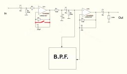
R3/C3 (and I'm assuming your diagram is accurate here and that there is nothing else connected to the inverting input) are an attempt to optimise the high frequency response (something that you will only see on square wave testing) and also possibly to improve high frequency distortion. All that is non applicable to the Di-FET input stage of the OPA2107.
R4/C4 are indeed a filter and its effect is way higher than the top of the audio band. 8k2 and 47pF will be around 3db down at 400kHz. The filter is possibly to stop RF interference.
R5/C6... R5 will set the gain of the stage in conjunction with whatever is in the BPF box. C6 rolls the response off at high frequency and aids stability.

Thanks! Explained everything very clearly. And the scheme I have given is absolutely accurate!R3/C3 (and I'm assuming your diagram is accurate here and that there is nothing else connected to the inverting input) are an attempt to optimise the high frequency response (something that you will only see on square wave testing) and also possibly to improve high frequency distortion. All that is non applicable to the Di-FET input stage of the OPA2107.
R4/C4 are indeed a filter and its effect is way higher than the top of the audio band. 8k2 and 47pF will be around 3db down at 400kHz. The filter is possibly to stop RF interference.
R5/C6... R5 will set the gain of the stage in conjunction with whatever is in the BPF box. C6 rolls the response off at high frequency and aids stability.
R1 limits ESD discharge current, protecting the op-amp, and RF input impedance to prevent local radio getting into your system. Note that minimum distortion may not be what your ears prefer. See Papa's JFET preamp.
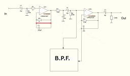
R3 is supposed to match R1 but the designer overlooked the fact that if used it should match R1+R2, not just R1. But it's pointless if you use FET input op-amps that have about zero input bias current, AND, if you use C2+R6 to block any offset passed on to OP2. Even if OP2 did see a bit of offset, it's output also has DC blocking so it would mater not. A little DC offset would be better suited to the polarized output cap. So, what I'm saying is this has a lot of boiler-plate circuit features that are mostly useless. The designer must have been inexperienced.
In my opinion, R2 here serves to discharge C1, and it also looks like a high-frequency filter. R4C4 and C2R6 are bandpass filters.R3 is supposed to match R1 but the designer overlooked the fact that if used it should match R1+R2, not just R1.
R2 provides the essential DC bias current route for the opamp input and its value also sets the input impedance of that stage. C1 AC couples the input and rolls off response at LF and DC. All standard stuff there 🙂
R1 and R3/C3 are something the designers felt were needed and I suspect the reasons are down 100% to that particular opamp type used and are to optimise distortion. Its not something that is routinely done and is not applicable to your chosen opamp
The 4559 is a slow device by todays standards with a slew rate of just 2V/uS. Not unlike a 741 really.
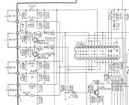
They provide a ground reference point for the inputs to stop them floating when not connected to anything. Its good practice to do that.
They also help protect the input selector chip from stray static charge because the input impedance of the chip on unselected inputs will be extremely high (probably hundreds of meg ohms). The ones on the line output also ground reference the mute transistors which is needed for proper operation.
They also help protect the input selector chip from stray static charge because the input impedance of the chip on unselected inputs will be extremely high (probably hundreds of meg ohms). The ones on the line output also ground reference the mute transistors which is needed for proper operation.
I removed the MUTE transistors and the input switching chip and put the relay on. This alone gave a better signal-to-noise ratio.
Fair enough 🙂 Those type of selector chips in general could and did give problems back in the day, I suspect they got damaged with static perhaps from 'hot swapping' and connecting stuff that was powered up.
In general, I listened a little more closely. On some compositions, the basses do not have enough meat with shorted R3C3. This is clearly audible if you close and open the R3C3 using a relay while listening. Otherwise, I heard absolutely no changes. I left R3C3 in place. They are more pleasant to my ears.Shorted out R3C3. I didn't catch any changes by ear. The oscilloscope did not detect any fluctuations in the circuit. I'm continuing the wiretapping.
Attachments
- Home
- Source & Line
- Analog Line Level
- Replacement 4559