Breakfast, coffee and morning walk over.
The circuit has features seen in Nelson Pass designs. Have a look at the A40 project on Passdiy and you can see and come to your own conclusions.
Some comon features are the omission of an input cap and large value NFB caps and the HF compensation method.
The preamp is not available from your source.
I would expect there is a blocking capacitor forming an RC circuit somewhere within and you should do a physical inspection.
I have never seen a Pass power amp with a d.c. servo and the 565 series preamp is probably intended for use with a power amp equiped with one.
A point which has not cropped up in previous discussion is power supplies. Many early designers from the 60's were older fellows whose taste was in classical music or Jazz.
Hi-Fi was relatively unaffordable back in those days and younger people could not afford to buy - so that was the general state of the market.
Classic programme material did not make the continuous demands for power in the bass region as present day Pop does and manufacturers were able to get away with modestly sized transformers.
That required some tailoring of the bass input so the transformer did not saturate and cause excessive electro magnetic radiation. It also helped filtering out rumble from phono sources.
The Japanese took over much of the market in the 70's and Hif-Fi became available to the younger generation whose interest was mainly in Rock music.
There was a growth Hi-Fi magazines started up to better inform the buying public. Much of their review comment on equipment was based on auditions usually on the more demanding Pop music. Compression of recordings seems to be a common feature in the Pop recording industry.
This implies higher output power, lower bass cut off frequencies and transformers that do not saturate - large beasts.
This influenced current designers to respond to those needs.
I expect your amp would weigh a fair bit and the build quality, once you take off the lid, to be substantial.
Michael Jonassen
Last edited:
ok, trying to make some headway here. If I am ordering new caps and have options of different values, should I consider raising the value of the NFB cap? It will stay an Electrolytic, but I have options of bipolar or non bipolar in stock 220uf, 330uf, 470uf and 1000uf. Right now I have on hand 220uf Elna Silmic II's. If I am lowering the RC of the input cap to 103 via a 4.7uf MKP, is there a need to have to use a bi-polar anymore for the NFB, or can I just use the standard Elna's I have since we are eliminating signal on that cap anyway by using the smaller input cap? If i raise the value of the NFB cap, won't this also mean I need a larger value input cap to raise the RC? Alternatively I can change the input resistor instead and keep a small value MKP as Andrew suggested.
I am not looking to redesign this amp. just to swap the input and NFB caps to better types or values. I understand that an electrolytic is going to remain as the NFB, just not sure if I should play around with raising its value and whether I need a bipolar since we are lowering the rc of the input cap. I also get that it is best to experiment, just need a good starting point.
I am not looking to redesign this amp. just to swap the input and NFB caps to better types or values. I understand that an electrolytic is going to remain as the NFB, just not sure if I should play around with raising its value and whether I need a bipolar since we are lowering the rc of the input cap. I also get that it is best to experiment, just need a good starting point.
I have tried a variety of caps in the C7 position and found subtle subjective differences in the sound.
The fun is in the finding out which you prefer.
Since Silmics have a good reputation by those who profess to know about such things you could start with these.
You need to live with them a while as one tends to think what one is used to is normal and something new is alien. It can take a while to appreciate differences as well - I think caps take some time to settle in.
Bipolar caps give protection against damage as much as anything else.
If there is a polar cap in C7 location it needs to be oriented correctly in consideration of the voltage across it.
If that voltage was positive in you orient the positive lead to the feedback network.
A problem would arise if an output transistor connected to the negative rail were to short out and present the rail voltage down the negative feedback section to C7.
Some designers will cover that situation by running a couple of signal diodes in parallel with C7. These would be reverse biased under normal conditions. In the fault condition as described these would conduct and limit the reverse voltage across C7 to 1.2 volts which will avoid damage.
Provided the a.c. signal across C7 does not exceed 1 volt peak then it will not cause any distortion.
You a pretty powerful amplifier. The peak voltage swing can be calculated from the output power rating. The result is divided by 680/22,000 to see if that value is within the 1 volt a.c. peak quoted.
If it isn't the question to ask is whether you make full use of the amplifiers full power capability.
If the foregoing seems to much then you would stick with bipolar or non polar caps.
Michael Jonassen
I noted the supply rails for your amplifier as + / - 85 volts.
From a guess your amplifier I expect the power output would be of the order 350 watts R.M.S. into 8 ohms. Peak volt a.c. voltage into that load would be an estimated 150 volts.
Dividing that by 680/22680 gives 4.5 volts peak across C7 and a pair of diodes reverse biased in parallel would cause some distortion since the peak voltage would exceed 1 volt peak. That diode strategy would reduce the distortion free output to less than 150 watts.
I guess that leaves little choice other than back to back caps - so you would need a pair of 470uF polarised values to get the equivalent of a standard bipolar cap.
Michael Jonassen
Mj,
you are using the completely wrong formula to determine the voltage across the NFB cap. If you read post6 para2, you would realise your model is wrong !!!!!
You are using a formula that determines the voltage across the resistor when no cap is present.
When the cap is present the combined R+C impedance at the test frequency must be substituted for the R. Then you have to split the AC signal voltage into reactive and resistive elements to find the voltage across the R and across the C. When you add these arithmetically you will find that the total exceeds the voltage across the R+C.
You can measure the actual voltages across the elements to check if you wish. In fact I recommend that you do the experiment to discover just how low the voltage is across the NFB capacitor. That is why the inverse parallel diodes do not interfere with normal amplifier operation. The diodes are only there to limit the cap voltage in a fault condition.
I consider it far more important to use a correctly sized capacitor in the NFB location than to worry about capacitor types and how they react to signal voltage when the value chosen is wrong.
Last edited:
That's an interesting question about whether you need a bipolar. With most amps, you know the polarity of the voltage across the cap, and therefore don't need a bipolar.I understand that an electrolytic is going to remain as the NFB, just not sure if I should play around with raising its value and whether I need a bipolar since we are lowering the rc of the input cap.
[ot]
Some designers manage to screw it up anyway, and put the caps in backwards. Interestingly those amps seem to work OK, despite the slight reverse bias on the caps.
[/ot]
Back to the point....
Yours is a symmetrical design, so it's pot luck what the polarity of the voltage across the cap is. You could measure it and, if there is any significant DC voltage across the cap, then you could replace it with a regular electrolytic and you'll know which way to connect it.
If there's very little voltage across the caps, you may be able to leave them out altogether. I'd check that first. With the amp switched off, disconnect the speakers (for safety). Then short each capacitor with a test lead. Then switch the amp on and check the DC offset at the speaker outputs. If the DC offset isn't too bad and isn't drifting, connect the speakers again and play some music. If the DC offset is still OK after the amp's nicely warmed up, then you don't really need the caps IMHO.
The output offset is determined by the voltage imbalance across the input pair.
This voltage is the difference between the input offset current times source resistance (DC) on the +IN and -IN sides.
If you short out the NFB capacitor then the -IN input sees the two feedback resistors in parallel as it's source resistance. That will change (probably drastically) the output offset.
This is what I call mixed AC and DC coupling.
A DC coupled amplifier amplifies DC just as much as AC in it's passband.
An AC coupled amplifier has a DC gain of 1 (the effect of the DC blocking cap in the NFB loop) and has a DC blocking capacitor at it's input.
I based my supposition on a recent design by "Silicon Chip" for an amplifier rated at 135 Watts RMS into 8 ohms and 200 Watts RMS into 4 ohms. It is known as Ultra LD Mk3.
This Australian Magazine sells the books that Self publishes. Their power amplifier designs embody much of Self's thinking.
The diode solution I mentioned is the exact one they now use. Two diodes are used whereas one might suffice for lowish powered amplifiers.
This amplifier was a revision of Ultra-LD mk2 published in an article in 2008 where the the use reverse connected diodes with a polar cap was explained.
This type replaced a non-polarised electro used in Ultra-LD Mk1 -they wanted to avoid any extraneous signal pickup which could happen with a bulkier part. Their designs/layouts are to cancel/minimise Class AB radiated fields.
The maximum signal level (across the polar NFB capacitor ) was then quantified at around 1 volt peak.
The magazine's Technical Editor and co-author of the Mk2 has a BE (Elec.) and access to the latest equipment.
Whether he measured or deduced this from theory I don't know but the information was good enough for me as it gave me some reference for comparisons without doing a lot more research.
The Acurus delivers a lot more power than 135 Watts into 8 ohms. I guess it would be capable of 350 Watts from the power rail values.
I knew there was a discrepancy between my calculated voltage at the inverting terminal and the peak of 1 volt at the NFB d.c. blocking cap in the case of the Ultra-LD Mk3.
Similar calculations told me the Acurus equivalent was 0.6 volts more and that concerned me.
A third reverse series diode might accomodate a peak signal increase, however one could not be sure it would prevent damage from a negative fault voltage in the feedback line. You could be sure there would be damage with a non polar cap that has no diode protection.
A 350 watt amp is an expensive purchase and repairs would also be expensive and the owner would not like that.
Theoretically the two diode solution would provide protection but compromise distortion at high power. That may not appeal to an owner who prides technical specifications.
The non polar cap is not a bad idea.
Andrew
I read your earlier post, I know peak signals across the NFB blocking cap diminish with reducing output power. Can you give me a reference to the material that quantifies some actual values at either end of the power range.
Michael Jonassen
Last edited:
if you need a higher voltage capability from the diode protection to the NFB cap, you can adopt a pair of series connected diodes to lift the Vf at start of conduction from 400mVpk to 800mVpk. Three in series would give a min Vf of 1200mVpk.
Then connect these duals or triples in inverse parallel and apply this group across the NFB cap.
I can't do the AC theory out my head so I will explain in a very approximate way how to arrive at the voltage across the NFB cap when an AC signal is being amplified.
Let's take 1kHz and maximum amplifier output of 40Vac (=56.6Vpk & = 400W into 8r0).
The NFB string is 27k + 1k (for an AC gain of 28times, +28.9dB) & a cap of 150uF (for an RC=150ms) The voltage at the bottom of that string is 0.0mVpk. The voltage at the top of the string is 56.6Vpk. The impedance of the 150uF @ 1kHz is 1/2PiFC ~= ohm
The total string resistance (that's my wrong approximation) is 27k+1k+1=28001ohms.
The volts drop across the top resistor is 56.6 * 27000 / 28001 = 54.577Vpk
The volts drop across the bottom resistor is ~56.6 * 1000 / 28001 ~2.021Vpk
The volts drop across the capacitor is ~56.6 * 1 / 28001 ~2.021mVpk That's my approximation coming in again.
Now add all those Vdrops together.
We have 54.577+2.021+0.002 = 56.600Vdrop. I know that the voltage across the capacitor is not in phase with the resistor Vdrop. I know from that that the total Vdrop should add to more than 56.6V. The biggest error in my approximation is in the smallest number that is approximately 90degrees out of phase with the resistive voltage. I will guess that the peak capacitor voltage when the 400W amplifier is outputting a maximum signal @ 1kHz is <4mVpk.
As frequency goes down the NFB cap volts drop increases. It's to minimise the increase that we should adopt a high enough value capacitor.
Could one of our many AC knowledgeable Members please provide the correct calculation?
ok, quick question. If I am lowering the value of the input cap from 10uf (electrolytic) to 4.7uf (mkp), should I lower the value of the bypass cap as well? right now it is a .1uf MKS4. I was planning on just trying a .1uf MKP4.
I suggest you avoid replacing the 10 uF cap with a 4.7uF MKP4. If you want the benefits of a better dielectric you could try replacing the .1 uF MKS4 with that value in MKP4.
There is an A250 photo on another forum showing wiring from the power supply caps to the amplifier modules is rather long.
This suggests Ian Finch's point in an earlier post over substituting physically larger components - the risk of pick up of radiated fields from the output stage - is likely.
Increasing the NFB cap to 470 uF will lower the -3 dB point of the NFB loop.
There is no significant difference in impedance between a 220 uF and a 470 uF capacitor at 1 kHz where the theoretical values are less than 1 ohm. However the differences will increase with decreasing frequency.
Increasing the NFB cap to 470 uF will lower the - 3db point of the NFB loop + the peak signal across this component will be halved in comparison to 220 uF.
Observations about physical size of components still apply with this component.
While some have studied/modelled capacitor characteristics - no doubt computer simulations are available - I believe Andrew T's calculations are good enough for diy purposes.
His worked example though is for a 50 watts R.M.S. amplifier with different component values. Applying this to the A250 shows the voltage across a 220 uF NFB cap gives a similar result claimed for the Silicon Chip Ultra-LD amplifier I looked at. The peak voltage across the NFB is less than 1 volt peak for each at rated power output - for frequencies 6 Hz or greater.
Many people including me, are happy listen at low output levels not often exceeding a watt or two, and peak voltage across the NFB cap will diminish. I have to be happy with that - my amplifiers have electrolytic NFB blocking caps of adequate value.
Response to low levels seems to have become an important aspect in some amplifier design - ever since someone touted subjective improvements from reducing phase shift at low frequencies.
In the case of high power design that enables listening at levels closer to live experience of an event and to feel the sonic impact - no doubt that would appeal to a wide audience.
Michael Jonassen
Last edited:
michael. i wasnt replacing 10uf elec. with 4.7mkp4. i was wondering what value mkp4 to use replace .1uf mks with, or if i should leave it out all together. i will try both and see. i will be using a 4.7uf Claritycap esa to replace the 10uf input cap. not sure what else i can do here other than stick with elec. and use nichicon muse bipolar. that is what i will be using for nfb cap in 220uf value. it will be bipassed with .47mkp4. not looking to redesign amp.just upgrade some components. this seems like the best combo based on the info posted in this thread unless i have interpreted it wrong.
mike
mike
That 0.1uF cap is only a "helper" for the HF audio range which is said to be mussed up by the cheap and dirty electro.
Once you upgrade the electro. to a good quality film type, the "helper" or "do-nuthin" cap is, IMHO, redundant, so why
retain it? It's not like you will improve matters by filling in the empty space with a boutique film type. Still, it's unlikely
to cause problems owing to the small size and similar properties to the upgraded main cap, if that's what you want to do.
Let's take 1kHz and maximum amplifier output of 40Vac (=56.6Vpk & = 400W into 8r0).
No, I stated what power/voltage my very approximate calculation was based on..............His worked example though is for a 50 watts R.M.S. amplifier with different component values. ............
Andrew,
Re; " Let's take 1kHz and maximum output of 40Vac (=56.6 Vpk & = 400W into 8r0)"
A 40 volt RMS capacity into 8 ohms = 200 watts RMS and 113 pk. volts.
A 56.56 volt RMS into 8 ohms = 400 watts RMS and 160 pk.volts.
A 20 volts RMS int0 8 ohms = 50 watts RMS and 56.56 pk.volts.
Your following calculations were based on 56.56 pk. volts or 50 watts RMS.
Having introduced the example of the 135 watts Silicon Chip amplifier into these discussions I felt obliged to compare this with the 250 watt A250 (mfilipello's actual hardware) in the light of your calculations.
This was possible from your example without quibbling over minor questions over which power output?
I am not here to nitpick and tried to avoid appearing that way in what I said so if I have come across that way I am sorry. In terms of the general thrust of your argument I thought I had given you due credit.
Michael Jonassen
and my quote is wrong.
I typed 400W into 8r0 and did not notice my error first time around nor second time around.
It should have stated 400W into 4r0
56.6Vpk is not the same as 56.6Vpp
I typed 400W into 8r0 and did not notice my error first time around nor second time around.
It should have stated 400W into 4r0
56.6Vpk is not the same as 56.6Vpp
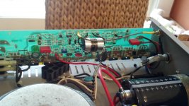
Well, finally got around to swapping caps and am having some issues. I am popping the rail fuses. One on each side. On the left channel, I am popping the positive rail fuse as circled in red in the picture. On the right channel, I am blowing the negative rail fuse. Both fuses blew after powering it on with heatsinks bolted back in place. When I first powered it on the left fuse blew but I did not have a fuse in the right channel. I had taken it out and forgot to put it back in. So when I first powered it up I had both fuses in place on left channel and only the positive rail fuse on the right side so I wasn't sure if I had an issue on that side until after I did some probing with meter and all looked good so I put a fuse in and it popped as soon as I flipped the power switch.
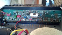
As yyou can see in the pics, I took the heatsink back off the left side. Putting both fuses in and powering the amp on nothing blows. So it would seem that there is a short caused by mounting the heatsink. I know that the transistors need to have the insulator installed and it was in place when the fuses blew. I have checked the areas where I soldered and I can not see any solder bridges. I only soldered 8 spots ( 4 caps. They are circled in white. Cap C7 is the large 220uf non polar electrolytic which was swapped with the 220uf Bi-polar Muse which is a direct replacement. Cap C6 was replaced with a .47 MKP4. This is the bypass cap for C7. I installed it with writing facing up, same as MKS4 which was there previously. C1 was removed and C2 was replaced with the Claritycap ESA in 4.7uf value upon recomendation from AndrewT and others. I actually installed this in the location of C1 as the mounting tabs were larger and easier to open up a bit for the lead diameter of the clarity cap. since these were in parallel to begin with, I don't see that as being an issue. The only other cap I swapped was C12. A .1uf MKS4 which I swapped for a .1uf mkp4.
Now, this amp was working fine before changing caps. Like I mentioned above, the left channel stopped blowing the fuse when i removed the heatsink. It only blew the positive fuse (red lead). I have not yet reinstalled the heatsink to see if the problem reoccurs. I did check the center leads on the transistors on the other channel and got no continuity to ground with one lead grounded to the chassis. I thought this side should be good but as soon as I put a fuse in the empty slot. it popped that one as well. (negative/blue lead).
Not sure what is going on. I immediately suspect a short to chassis through the transistor but this does not seem to be the case. I had to leave for work and won't get a chance to start checking further til tonight. any suggestions would be welcome. Pictures of each board and diagram attached
Mike
Attachments

update, pulled the heatsink back off right channel and inspected work and found no solder bridges. installed a fuses in both slots on right channel. powered it on and no popped fuses. once again, seems that heatsink is to blame but all insulators are installed and I could not find a short to ground.
thoroughly confused.
thoroughly confused.
Without knowing the assembly details for mounting the sinks to the chassis, I can only assume they are intended to be insulated from each other. To blow fuses, there has to be a potential between sink and mounting points so test this first. OK, now you measure something on the sink, what is it - a rail voltage or another easily located source from the connections?
Check the sink(s) over to find any wires or connectors that look intentional and find what's supposed to be there. Again, identify the source.
Assuming that the insulators are supposed to do just that, 'better also find out why they don't now. Are they damaged so that they allow the fasteners to short across the mount as you assemble? Test, step by step, to identify where it occurs. Looking at the insulation, is there a fragile item like a washer or piece of sleeving scrunched up, cut or missing? Maybe the insulation is supposed to be replaced each time it is disassembled? 🙁
- Status
- Not open for further replies.
- Home
- Amplifiers
- Solid State
- replacement 220uf bi-polar options