Hi Guys,
somebody can tell me if possible to replace the KDA0316 DAC by PCM1754. Thank You! Maxpou
http://www.datasheetcatalog.com/datasheets_pdf/K/D/A/0/KDA0316.shtml
http://www.datasheetcatalog.com/datasheets_pdf/P/C/M/1/PCM1754.shtml
somebody can tell me if possible to replace the KDA0316 DAC by PCM1754. Thank You! Maxpou
http://www.datasheetcatalog.com/datasheets_pdf/K/D/A/0/KDA0316.shtml
http://www.datasheetcatalog.com/datasheets_pdf/P/C/M/1/PCM1754.shtml
It is not pin compatible, so you definitely wouldn't be able to simply remove one and solder in the other.
Hi,
yes i know that i gonna design the PCB, but i would like to know for bit clock input, audio data input, system clock and for the selection of audio data if is compatible. thank you! Maxpou
yes i know that i gonna design the PCB, but i would like to know for bit clock input, audio data input, system clock and for the selection of audio data if is compatible. thank you! Maxpou
Compairing the two data sheets I don't think it will work. The reason is that the Samsung DAC uses two word clocks; one for left and one for right and they are not present for a complete cycle of the data. I have never seen this before.
The Ti part uses the industry standard method of having one word clock with left indicated by one state of the line and right by the other.
If you are good at logic circuits it may be possible to create a circuit to convert the two word clocks into one that is compatible with the TI chip.
Regards,
Andrew
Thank you for reply!
but where are you found this information? I read the datasheet many time and i dont found it. Maxpou
but where are you found this information? I read the datasheet many time and i dont found it. Maxpou
For the samsung part the timing diagrams show the two left right word control clocks WDCLK1 and WDCLCK2 clocks on page 508 in both timming diagram 1 and timming diagram two.
For the BB part the timming diagrams are on page 15 and show just one combined LRCK for left and right word control.
Regards,
Andrew
For the BB part the timming diagrams are on page 15 and show just one combined LRCK for left and right word control.
Regards,
Andrew
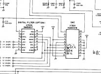
All the signals bar BIT CK, LRCK and DATA are irrelevant to the PCM1754. All you need to find or generate is a system clock signal synchronous to the data.
maxpou said:Thank you guys for reply,
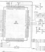
but you need a other document sorry! In my cd player the dac use only WDCLK1 as in this schematic.
rfbrw: can you explain more because i don't understand?
thnak you! maxpou
There are two WDCLK modes for this DAC. See the timing diagram headings, the modes are selected by MS. When MS is high, WDCLK is just LRCK * 2. You can probably just ignore this though, since it's not needed for the TI DAC.
As rfbrw says, all the signals you need are there (LRCK, BCLK, DIN) except for the system or master clock input. I think you can find that on the SM5807 XTI pin. It should be 16.9344MHz, which is suitable for PCM1754. PCM1754 can run at 5V, so level shifting is not required. I think this should work without much trouble, but obviously you need a whole new output stage.
Hi
How should selected the FMT pin in PCM1754?
i forgot to tell you i don't have the digital filter (sm5807). I changed my output stage with only a jfet source follower.
Thank you! Maxpou
error401 said:
There are two WDCLK modes for this DAC. See the timing diagram headings, the modes are selected by MS. When MS is high, WDCLK is just LRCK * 2. You can probably just ignore this though, since it's not needed for the TI DAC.
As rfbrw says, all the signals you need are there (LRCK, BCLK, DIN) except for the system or master clock input. I think you can find that on the SM5807 XTI pin. It should be 16.9344MHz, which is suitable for PCM1754. PCM1754 can run at 5V, so level shifting is not required. I think this should work without much trouble, but obviously you need a whole new output stage.
How should selected the FMT pin in PCM1754?
i forgot to tell you i don't have the digital filter (sm5807). I changed my output stage with only a jfet source follower.
Thank you! Maxpou
Hi,
i think have understand, i thought SCK was the same think then WDCLK, but SCK and master clock is the same think! I changed my master clock with PLL1705 from TI. Maxpou
i think have understand, i thought SCK was the same think then WDCLK, but SCK and master clock is the same think! I changed my master clock with PLL1705 from TI. Maxpou
You can connect the PCM1754 directly to the KS9211B as the TI chip has the digital filter built into it.
- Status
- Not open for further replies.
- Home
- Source & Line
- Digital Source
- replace DAC