Disagree about what? I agree that measuring the line out with a scope would reveal whether the noise track is 0dB. But I can’t arrange a scope on short notice and in my world I already proved that it is not 0dB. Actually, you can download the test tracks that I used here (245MB):
Download test tracks
Once you have downloaded the .ZIP file, unzip it and burn the audio tracks on a CD. Track 1 is the random noise track that I used and track 2 is the sine sweep.
As for my suggestion that bad timing could depress HF noise in the Alpha 9, it’s only a suggestion. I don’t agree nor disagree with you about whether this is in fact happening. By the way, I have seen several claims on the web that replacing the clock of the Alpha 9 improved the sound. And the fact that Arcam upgraded the master clock and the clock buffering and clock output distribution circuitry in the CD23T, also seems to indicate that there might be a timing problem in the Alpha 9. Anyway, if it isn’t the clock/timing and it isn’t a 0dB limiting artefact, then what else could selectively cause a depression of HF noise and not HF pure sine waves?
Now this is why you need to verify your methods... and a scope is essential, it would have shown this.
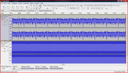
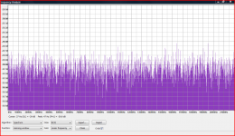
Track 1 of your test files is anything but random noise. The picture shows your file and a true white noise file for comparison. As soon as I listened to yours I could tell it didn't sound right. You can hear the rhythmic clicking. The very large negative going spikes could well give results from different DAC's as witnessed by my 0db observations that I linked to earlier. The first spectrum plot is yours, the second mine. Same settings.
Attached is a true 0db white noise file. Its LOUD so be careful.
WHITE NOISE 0db
And here is a more level friendly -20db version with fade in and out.
WHITE NOISE MINUS 20DB
Attachments

Thanks for the files. I’ll try them as soon as I’ve got myself some writable CDs. 🙂 The track 1 signal is indeed not white noise but is said to be "pseudo-noise". I found the following info regarding frequency response measurement in the online user manual of my sound analyzer program:
So this basically means two things. First, my measurments were spot on 🙂 and second, the HF noise is degraded by the sample clock variations of the Alpha 9. Such clock variations are apparently not (or to a much lesser extend) present in the CD23T. My guess is that this also causes the relative lack of HF detail/definition in the Alpha 9..Important! To use this properly you must be playing the specified audio track (from the test track CD or DVD) as indicated at the top of the program window. The measurement is matched to the test signals provided on the specified tracks. You can choose between two types of signal by selecting between the "pseudo noise" and "sine sweep" buttons above the graphs.
• "Pseudo-noise" test signals that sound like Pink Noise are easy on the ears for extended sessions. The accuracy using pseudo-noise at highest frequencies, however, can be degraded by sample clock variations.
• Sine Sweep signals provide the cleanest and most accurate measurements, as well as being able to drive speakers at specific SPL levels. This is the preferred choice for frequency response measurements and should be used for all high-frequency measurements.
(http://www.daytonaudio.com/OmniMicV4/index_OmniMic.html)
Try the minus 20db file and see if you get different or similar results between the players. I can do a true pink noise one to if you wish.
When it comes to acoustic measurement and techniques I'm out of my depth, its not a subject I know enough about to make informed comment and advice. I would however be suspicious of results having seen the large repetitive spike in your file as that could come across differently via different dac's.
When it comes to acoustic measurement and techniques I'm out of my depth, its not a subject I know enough about to make informed comment and advice. I would however be suspicious of results having seen the large repetitive spike in your file as that could come across differently via different dac's.
Could it be possible (just because I'm curious) to have a photograph of each player between the chinch output and the close layout (aop/transistors, caps...) ?
Are they really similar ???? Did you check all the differences between the two players (passive parts and active parts) ? Are there different values with the passive parts, etc ? You could do a little some reverse ingeneering if you are sure all the active parts are similar (the optic block as well ?) !
Did you finish to test all the bypass possibilities (with and without FC and FM) on CV47/48 ! I don't think the cap are involved anymore in the result between cd23 and cd9 : the Panasonic FC I choosed give a subjective higher high end (and bass) : loudness type as you find yourself... So if high are missing and any LP (passive or active) filter are involved, you should try to have a list of the différences between parts ! B plan, B door : for a non-technician as I am ! (non scientific method 😉 )
I used the -20db and 0db white noise signals and, in contrast to the "pseudo noise" FR, there is no difference between the players in the measured average FR with white noise. I would appreciate it if you could also provide a true pink noise file. Thanks. 🙂Try the minus 20db file and see if you get different or similar results between the players. I can do a true pink noise one to if you wish.
When it comes to acoustic measurement and techniques I'm out of my depth, its not a subject I know enough about to make informed comment and advice. I would however be suspicious of results having seen the large repetitive spike in your file as that could come across differently via different dac's.
No problem, I'll do that a bit later (I need a different PC with Dropbox on it). So, an interesting result so far......
Hi Eldam. There are many differences between the player’s DAC board, the power supply, the clock circuitry, and the transport and laser unit. But as far as I know, the actual Ringdac chips are the same and the audible difference between the players should be subtle, which it isn’t, especially in HF detailing.Could it be possible (just because I'm curious) to have a photograph of each player between the chinch output and the close layout (aop/transistors, caps...) ?
Are they really similar ???? Did you check all the differences between the two players (passive parts and active parts) ? Are there different values with the passive parts, etc ? You could do a little some reverse ingeneering if you are sure all the active parts are similar (the optic block as well ?) !
I didn’t finish testing all bypass possibilities. I broke my left arm a few days ago in an indoor skiing accident so I can’t do any work on the caps right now. Currently C36/44/45/47/48 have all been changed with Panasonic FC, no bypasses. But I’m sure that doesn’t relate to the measured drop in high frequency response in the Alpha 9 when a so called "pseudo noise" (pink noise?) signal is played.Did you finish to test all the bypass possibilities (with and without FC and FM) on CV47/48 ! I don't think the cap are involved anymore in the result between cd23 and cd9 : the Panasonic FC I choosed give a subjective higher high end (and bass) : loudness type as you find yourself... So if high are missing and any LP (passive or active) filter are involved, you should try to have a list of the différences between parts ! B plan, B door : for a non-technician as I am ! (non scientific method 😉 )
Like I said, there are many differences between the two players, perhaps most notably the clock circuitry. According to the manual of the measurement equipment I used, the HF drop is caused by sample clock variations (jitter). Possibly a better low jitter clock could improve detail in the Alpha 9..
I tried it. Again exactly the same frequency response for both players..😕
OK, well that seems to point to the rhythmic glitches somehow causing a difference to the way each players dac interprets them.
You could (just for curiosity) try reducing the amplitude of your pseudo noise track in Audacity for example and resample it to a level to bring those glitches below clipping level.
You could (just for curiosity) try reducing the amplitude of your pseudo noise track in Audacity for example and resample it to a level to bring those glitches below clipping level.
Here’s what I think is going on..
The pseudo noise signal was especially designed to measure frequency response. It does the job for the CD23T (producing exactly the same FR curve as with the pure sine sweep), but not for the Alpha 9. Now the signal appears to consist of a continuous repetition of the same noise-like fragment of about 1 second duration (see the first picture of your post #103). If there are sample clock variations in a player, then construction of the FR curve by addition and averaging of the reproduced fragments would degrade the higher frequencies. So the HF effect is an artefact of how the software operates and not as such acoustically present in the measured sound.
If this is indeed true, then it could be an interesting way to assess sample clock variations or jitter. And the effect may be replicable with a repetitive signal of (e.g.) some white noise fragment. I might try that, but I’m totally unfamiliar with sound editing software, so it may take a while.. 🙂 I also suspect that the length of the fragment (in seconds) must be the same as the length of the single pseudo noise fragment and/or possibly the strange spike in the pseudo noise fragment serves as a separator signal for the software..
You could certainly experiment with Audacity,
http://www.diyaudio.com/forums/soft...ing-using-audacity-get-you-started-guide.html
It would be easy to create a white (or pink) sample of say 1 second and then copy and paste it together, and then after say 5 copies of that, copy and paste the whole lot again and so on. That way you can soon create a 30 or 60 second track. You could then cut the noise every (say) 1 second by adding a gap of 50 or 100 milliseconds. That would give a repetitive track with the same 1 second sample repeated over and over.
What is actually occurring with you players is open to speculation and I don't know how you could prove that. I keep going back to my experience of how my two players handled white noise at 0db and those pictures I linked to earlier highlight that.
Your pseudo noise track... I'll resample it later today and lower the level and then you can see if the same effect occurs.
Here is your original noise track resampled to -20db peak level. If timing errors are the cause then I guess it would still give the same 'difference between players' result.
https://www.dropbox.com/s/3sbhhz55462yx5l/Resampled Track No 01.zip?dl=0
https://www.dropbox.com/s/3sbhhz55462yx5l/Resampled Track No 01.zip?dl=0
Interesting result... and I'm a little surprised too.
I've no real answer for you on that I'm afraid although it would be very interesting to visually look at the output of each player on a scope and see if there is any difference. Something in the nature of that file obviously causes this difference. I just wonder if this is a 'real' effect or whether its an artefact of what could be (and I don't know for sure it is so) an 'invalid' type of signal that bears no relation to music. The difference in HF level is very marked in that track, and yet the continuous random white and pink noise don't show that.
I've no real answer for you on that I'm afraid although it would be very interesting to visually look at the output of each player on a scope and see if there is any difference. Something in the nature of that file obviously causes this difference. I just wonder if this is a 'real' effect or whether its an artefact of what could be (and I don't know for sure it is so) an 'invalid' type of signal that bears no relation to music. The difference in HF level is very marked in that track, and yet the continuous random white and pink noise don't show that.
Maybe the Alpha 9 is more correct than the CD23T ?
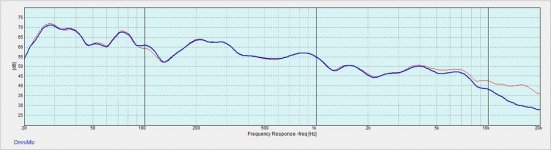
Alpha9 resembles Mooly's spectrumplot better from 4khz to 8khz in first FR graph, cd23t there has almost no db loss, Alpha9 is like spectrumplot around -3.5db?
Alpha9 resembles Mooly's spectrumplot better from 4khz to 8khz in first FR graph, cd23t there has almost no db loss, Alpha9 is like spectrumplot around -3.5db?
You wouldn’t see anything out of the ordinary on a scope. Like I said (and as the software manual indicates), the HF degradation in the presence of jitter is an artefact of how the software samples the acoustic signal and constructs the FR curve from summation and averaging of repeated similar noise samples. Is there any way to demonstrate jitter on a scope?Interesting result... and I'm a little surprised too.
I've no real answer for you on that I'm afraid although it would be very interesting to visually look at the output of each player on a scope and see if there is any difference. Something in the nature of that file obviously causes this difference. I just wonder if this is a 'real' effect or whether its an artefact of what could be (and I don't know for sure it is so) an 'invalid' type of signal that bears no relation to music. The difference in HF level is very marked in that track, and yet the continuous random white and pink noise don't show that.
- Home
- Source & Line
- Digital Source
- Replace caps of Arcam Alpha 9 CDP?