I tried NTE49/50 (TO220) as replacements for the 2n5020/22 on my PC14. This was before debit card invention allowed individuals to buy from Newark/digikey/mouser/arrow. The twisted leads to match the EBC holes broke after a year or 18 months, then when I tried to replace the NTE49/50 the PC lands came unglued. Ended up scrapping the board and building an Apex AX6 out of Nema-CE board & 72 wires. Waste of 200 hours work if EBC transistors could have been bought with 20 mhz ft or above. The corrogated heat sinks on my dynakit boards were easily removeable.
You could always buy from Digikey or Mouser back then - they accepted checks and money order. Newark, Arrow, the others - not so much. Mouser didn’t sell anything but TIPs and the MJE172/182 series - and 2N3055’s. Whoopee. Digikey too. Real amplifiers need better parts. But Digikey DID carry a limited number of Panasonic devices - including the 2SC1567 and 2SA794. They found their way into just about everything back in those days. The only issue was they were only 120 volt instead of the 160 or 180 that are typical today. I’d still be using them if I could get them. The leads were thinner and more flexible than what’s typical of TO-126 parts today - perfect for leadforming into an old TO-5 slot. Get in your DeLorean and give Digikey a call and you could have kept your original boards. Digikey had them in stock LONG after Panasonic discontinued them - when MCM stopped DK still had some.
Those C1567/A794 show up as surplus every now and again. Last batch I had (it’s been years now, but…) came from Skycraft.
Those C1567/A794 show up as surplus every now and again. Last batch I had (it’s been years now, but…) came from Skycraft.

hi has been a long time since I post something I'm just going to post this image of the Tigersaurus 210 here as purpose of documentation here is the idea I have to replace all of those vintage RCA transistors with a new one and new heat sink designs

It looks like you could lay down a ECB-type TO-126 in the right orientation and make the connections to the board using tinned bus wire of the appropriate gauge. With the room that the old RCA transistors took with their relatively enormous heat sinks, you could slip a TO-220 type heat sink (or an aluminum L-bend for that matter) under the part and get by just fine in terms of voltage rating (the old RCAs were only good for 90V anyway) and power dissipation. The new TO-126s are complete overmold, so the heat sink would be isolated - a plus. I would use a squirt or two of hot melt or silicone or epoxy to make sure the new part doesn't get jacked around and broken off.
Hi yes I thought about all that the heat sink can be solder to the PCB I got the TO-126 in place and yes I can change the traces to accommodate them, the heat sink part number is 634-10ABPE


I've been looking to use 2N5680/2N5682 as replacements for 40409/40410.
TO-39, 120V, 40 hfe @250mA, 30MHz, 1W/10W.
Bought a few last year, Farnell still has them listed, NPN in stock, PNP on a 6 week lead time.
Will need to add a heatsink similar to the original 40409/10.
TO-39, 120V, 40 hfe @250mA, 30MHz, 1W/10W.
Bought a few last year, Farnell still has them listed, NPN in stock, PNP on a 6 week lead time.
Will need to add a heatsink similar to the original 40409/10.
have you check Mouser? they have them heat sink I have to check TO-39 CASE
610-2N5680 Mouser 610-2N5682
610-2N5680 Mouser 610-2N5682
Years ago, I reused the 40409(etc) heat sinks by soldering metal TO-39/TO-5 transistors into the old heat sink. Bang the original ~TO-39 out with a hammer and punch. But given other issues with this amp, today I would replace the PCB and update the circuit with a "Blameless" circuit. The old outputs were slow, but you could still use them.
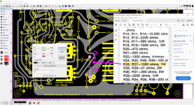
hi I completed the PCB and what I did is reconfigured the traces to fit TO-126 transistors, question is there any extra modification that can be added to the circuit? Yes, I understand that there are newer design that I know, but this will be nice as reference for those that own the design and have images here that
I'm going to post as I go, the first image is how originally goes for those RCA's 40409's the second image is the PCB with the modification for all RCA 40409/etc, those heat sinks can be solder to the PCB too.
with no modification

with newer heat sink design

I'm going to post as I go, the first image is how originally goes for those RCA's 40409's the second image is the PCB with the modification for all RCA 40409/etc, those heat sinks can be solder to the PCB too.
with no modification
with newer heat sink design
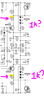
Can you guys help here I was doing the PCB and I notice that on schematic R26, R27 the values are 100R both but on the BOM the value are different they are 1K?
Attachments

- Home
- Amplifiers
- Solid State
- Replace 40409, and 40410 with what?