ok stupid me. did i notice an output at the back? No.sorry, 1st post so hello to all and another echocord problem needs solving.
just got a 62a echocord.
the big problem being i only seem to get the a delayed signal from the machine. always a 0.5sec (approx) time between hitting a note and getting any sound back from amp.
the reverb control does not seem to change this. the tone control (pulled out or pushed it) also doesnt seem to do anything.
the switches all seem to work but i cant get rid of this latency.
i am outputting from the remote circuit.
the middle knob is the only one that seems to do anything. this seems to work fine (though i cant remember what it is called for now) its the duration of the echo.
anyone have any thoughts?
am i wired up correctly?
is it perhaps a problem with the reverb control?
any ideas welcome.
Thanks
TIm
have i found it now? yes
Does it now work perfectly? seems to.
Fantastic machine.
these things dont come with a manual.
though if it did i would have probably thrown it away unread anyway.😱
Hello all!
I have an S65 and I am looking for those replacement 6V bulbs (x2) for the front control panel. I don't have the model number as I lost the burnt ones...
Does anyone has the model number and knows where to find them?
Thanks!
Guillaume
I have an S65 and I am looking for those replacement 6V bulbs (x2) for the front control panel. I don't have the model number as I lost the burnt ones...
Does anyone has the model number and knows where to find them?
Thanks!
Guillaume
Last edited:
6.3V bulbs
ladaniva
I have tried but not find any.
I have mounted small round radio-scale bulbs (6.3V) where the threads are and soldered a cable from the bottom contact to the other mount.
You need them otherwise the filament voltage will be a bit to high. To high filament voltage shortens the life of the tubes.
Well, i'm almost done completely restoring my echocord 62. i finally figured out the problem with the buttons. It turned out to be a bad head and i'm having it rewound right now. i found a source for bulbs at interlight.com if anyone is looking for them. They have 31 mm bulbs that will work if you gently spread the blades of the fixture apart.
i am finishing up replacing all the capacitors, electolytics, signal and the ceramics. But there is one cap in my machine that isn't on the schematics. It is a 5000 pF 500 v AC cap going from the voltage selector to the chassis. It is a yellow cap like the signal ones except it's AC. It looks to be in bad shape but i can not figure out what it is there for and why it's not on the drawings. Does anyone else have this?
i am finishing up replacing all the capacitors, electolytics, signal and the ceramics. But there is one cap in my machine that isn't on the schematics. It is a 5000 pF 500 v AC cap going from the voltage selector to the chassis. It is a yellow cap like the signal ones except it's AC. It looks to be in bad shape but i can not figure out what it is there for and why it's not on the drawings. Does anyone else have this?
i am finishing up replacing all the capacitors, electolytics, signal and the ceramics. But there is one cap in my machine that isn't on the schematics. It is a 5000 pF 500 v AC cap going from the voltage selector to the chassis. It is a yellow cap like the signal ones except it's AC. It looks to be in bad shape but i can not figure out what it is there for and why it's not on the drawings. Does anyone else have this?
It is there to help suppress high frequency noise from the AC mains. Cut it out and don't replace it unless you have one on hand of the appropriate ratings. Check for instance this page for more info. You cannot use just any capacitor in this location.
Thanks, i know i can't just replace it with a normal cap. i was just wondering what it's function was since it doesn't appear on the schematic. i'll try to remove it and see what difference it makes if any.
Help with a s65 Echocord
Good morning all, I have a problem with a Dynacord s65 I'm restoring and I find no echo signal I measured voltages and there is no voltage on the transformer Secondary DCN 601. I measured impedances and there seems to be OK if I give information on this. Greetings to all!
Good morning all, I have a problem with a Dynacord s65 I'm restoring and I find no echo signal I measured voltages and there is no voltage on the transformer Secondary DCN 601. I measured impedances and there seems to be OK if I give information on this. Greetings to all!
Attachments
Hello Rubenjhon,
Do you have a scope?
If so you should see a hf wave form on the head LF4.
But that's the erase head.
Did you check the power supply; HT, ff etc on each tube?
Can you inject a signal (sinus) into an input an follow it to Ro 5?
Come back again with the results.
Do you have a scope?
If so you should see a hf wave form on the head LF4.
But that's the erase head.
Did you check the power supply; HT, ff etc on each tube?
Can you inject a signal (sinus) into an input an follow it to Ro 5?
Come back again with the results.
Hi Tarzan, if I measured all the voltages and they seem fine, I'm almost certain that the transformer DCN 601 is open, if not voltages recorded at the high school and even in their heads.
how to test the transformer is disconnected and apply a voltage to the primary and see if it leads to the secondary.
Greetings!
how to test the transformer is disconnected and apply a voltage to the primary and see if it leads to the secondary.
Greetings!
Hi there!
Sorry for resurecting this post but I am looking for a pair of Dynacord 3553 transfos for my Super S-65.
If someone has a pair for sale, I'll be your man!
Many thanks!
Guillaume, Quebec, Canada
Sorry for resurecting this post but I am looking for a pair of Dynacord 3553 transfos for my Super S-65.
If someone has a pair for sale, I'll be your man!
Many thanks!
Guillaume, Quebec, Canada
if I have a Super Dynacord S65, in operation, but I could not run the echo boy you hang up photos tomorrow.
greetings from Lima - Peru.
greetings from Lima - Peru.
Ok thanks!
Can anyone tell me where wire no.17 (on the picture below) has to go? I can't figure it out. For now it doesn't go anywhere on my machine. My guess is that it goes on pin 3 of the output jack. I am trying to get the "reverb only" function when pulling the tone knob. I always have wet and dry signals on either position of the push-pull knob.
![URL]](/community/proxy.php?image=http%3A%2F%2F%5BURL%3Dhttp%3A%2F%2Fimageshack.us%2Fphoto%2Fmy-images%2F855%2Fi789.jpg%2F%5D%5BIMGDEAD%5Dhttp%3A%2F%2Fimg855.imageshack.us%2Fimg855%2F7185%2Fi789.jpg%5B%2FIMGDEAD%5D%5B%2FURL%5D++Uploaded+with+%5BURL%3Dhttp%3A%2F%2Fimageshack.us%5DImageShack.us%5B%2FURL%5D&hash=55e2a580100c02b09d0e5e8e9c93bb66)
The wire no.17 is coming from here:
![URL]](/community/proxy.php?image=http%3A%2F%2F%5BURL%3Dhttp%3A%2F%2Fimageshack.us%2Fphoto%2Fmy-images%2F11%2Femsq.jpg%2F%5D%5BIMGDEAD%5Dhttp%3A%2F%2Fimg11.imageshack.us%2Fimg11%2F1130%2Femsq.jpg%5B%2FIMGDEAD%5D%5B%2FURL%5D++Uploaded+with+%5BURL%3Dhttp%3A%2F%2Fimageshack.us%5DImageShack.us%5B%2FURL%5D&hash=0ba94b3ae552a1b99eda8c454777ab3a)
Many thanks!
Guillaume
Can anyone tell me where wire no.17 (on the picture below) has to go? I can't figure it out. For now it doesn't go anywhere on my machine. My guess is that it goes on pin 3 of the output jack. I am trying to get the "reverb only" function when pulling the tone knob. I always have wet and dry signals on either position of the push-pull knob.
The wire no.17 is coming from here:
Many thanks!
Guillaume
Hi, Can you tell us where the other side of the cable is attached to?
On the lower picture it seems to be a trimmer and 2 resistors.
Pin 3 of the output jack? Don't know...
What is connected to one end? (resistor and /or capacitor values)
That way we may be able to find on side of the connection on the schematic and then to find the other side is fairly easy.
On the lower picture it seems to be a trimmer and 2 resistors.
Pin 3 of the output jack? Don't know...
What is connected to one end? (resistor and /or capacitor values)
That way we may be able to find on side of the connection on the schematic and then to find the other side is fairly easy.
Ok got it!
This cable goes to the switch on the DIN output connector. This one shorts the input (or output?) to ground when there is nothing connected to the output connector. For example, if you only use the Instrument Input jack 1 and use Pin 3 on the same jack for output (and nothing connected to the output connector), you'll get some squealing when you'll turn up the volume if the cable no 17. is not shorted to the ground.
Now I am looking for this special kind of DIN connector with the switch... Anyone knows where to get one?
And I am still looking for a pair of Sennheiser 3553 transfos...
MANY thanks for your help!
Guillaume, Quebec, Canada
Hi everybody,
First post overhere...found this thread while researching info about my Klemt Echolette S NG51 "Goldcage" from 1962 which im trying to repair at the moment.
Why post that in this thread you might ask...well Klemt was acquired by Dynacord and actually the S62 is very similar to the Klemt. Take off both transformer inputs and you have the Echolette....
The story so far:
Got this Klemt cheap and it is stacked with all the original Telefunken ECC83 Smooth Plates 🙂 So even when not working i have agreat pre amp was my thought, and looking at 2nd hand prices for these kind of tubes...well...a good investment to buy this broken Klemt.
So when it got in by mail i tested it but only the pre amp was working, no echo..did some measurements and first thing that i did was swap the bridge rectifier and smoothing caps, also replaced one of the resistors in the power supply and some very old capacitors...
Turned it back on and yes i could hear the tape now and faintly something is also recorded. But all sound is infected with heavy distortion.
So desoldered the rec heads and only one is within its specs of about 1.1k, the other two are around 3meg so those are busted and will need relapping.
One of the playback heads is also gone and when engaged by the pull up switch on the 'nachhalldauer' only adds hum.
But progress is progress and its working more than it did when i got it...
I get a HF signal on the bias transformer but this is only when the machine is cold. After 5 minutes it just goes flat, no more oscillation. But there is oscillation and that makes me happy and it is good to know the bias transformer isn't dead.
What is happening?
Here are the measurments i have taken with all tubes installed.
Given the follow voltages from the DC mains:
A1= 335V
A2= 252V
A3= 172V
All heaters measure correctly in AC, about 6,4V AC.
Ive measured all pins on the tubes and about some voltages i have my doubts.
On tube 2 im getting a positive voltage of 1V on the grid 2 and cathode 2
On tube 4 im getting postive voltages of 2.7V on grid 1 and about 30V on grid 2.
On tube 5 im reading 10V on both cathodes.
Are these voltages right?
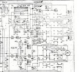
Ive attached the NG51 schematic and reading the tube is pin 1 anode on the left and pin 6 anode on the right.
First post overhere...found this thread while researching info about my Klemt Echolette S NG51 "Goldcage" from 1962 which im trying to repair at the moment.
Why post that in this thread you might ask...well Klemt was acquired by Dynacord and actually the S62 is very similar to the Klemt. Take off both transformer inputs and you have the Echolette....
The story so far:
Got this Klemt cheap and it is stacked with all the original Telefunken ECC83 Smooth Plates 🙂 So even when not working i have agreat pre amp was my thought, and looking at 2nd hand prices for these kind of tubes...well...a good investment to buy this broken Klemt.
So when it got in by mail i tested it but only the pre amp was working, no echo..did some measurements and first thing that i did was swap the bridge rectifier and smoothing caps, also replaced one of the resistors in the power supply and some very old capacitors...
Turned it back on and yes i could hear the tape now and faintly something is also recorded. But all sound is infected with heavy distortion.
So desoldered the rec heads and only one is within its specs of about 1.1k, the other two are around 3meg so those are busted and will need relapping.
One of the playback heads is also gone and when engaged by the pull up switch on the 'nachhalldauer' only adds hum.
But progress is progress and its working more than it did when i got it...
I get a HF signal on the bias transformer but this is only when the machine is cold. After 5 minutes it just goes flat, no more oscillation. But there is oscillation and that makes me happy and it is good to know the bias transformer isn't dead.
What is happening?
Here are the measurments i have taken with all tubes installed.
Given the follow voltages from the DC mains:
A1= 335V
A2= 252V
A3= 172V
All heaters measure correctly in AC, about 6,4V AC.
Ive measured all pins on the tubes and about some voltages i have my doubts.
On tube 2 im getting a positive voltage of 1V on the grid 2 and cathode 2
On tube 4 im getting postive voltages of 2.7V on grid 1 and about 30V on grid 2.
On tube 5 im reading 10V on both cathodes.
Are these voltages right?
Ive attached the NG51 schematic and reading the tube is pin 1 anode on the left and pin 6 anode on the right.
Attachments
Yesterday did some more reading and searching and came across the SM for the Echolette E51. Actually this is the same layout as for the NG51 but on the E51 schematic they conviently enough wrote down all the voltages for all tubes and psu!
Just what i needed.
Know i know for sure that my psu dc voltages are correct, that the voltages on the bias tube are correct etc.
I will be sending all of the heads of to JRF Magnetic Head Company in the USA to all be reconditioned.
After the heads come back the bias transformer will have the load that's expected...i think my bias disappears because the two broken heads become saturated after 5 minutes with a to high load...
Anyway this machine will live again....
Hello there!
Can you tell me if you found the problem with it? Cause i got the same issue here,
i bought an old NG51 but the echo function doesn't work, i got a nice preamp though..
Any idea what it could be?
Nick from France
Can you tell me if you found the problem with it? Cause i got the same issue here,
i bought an old NG51 but the echo function doesn't work, i got a nice preamp though..
Any idea what it could be?
Nick from France
So desoldered the rec heads and only one is within its specs of about 1.1k, the other two are around 3meg so those are busted and will need relapping.
One of the playback heads is also gone and when engaged by the pull up switch on the 'nachhalldauer' only adds hum.
Sorry,but to me the windings of the respective heads are broken. There's no use in relapping them, which is quite a mechanical process of polishing a head's contact surface. I don't know any shop, IRF included, that will do a head rewinding for you.
Ive measured all pins on the tubes and about some voltages i have my doubts.
On tube 2 im getting a positive voltage of 1V on the grid 2 and cathode 2
On tube 4 im getting postive voltages of 2.7V on grid 1 and about 30V on grid 2.
On tube 5 im reading 10V on both cathodes.
Are these voltages right?
Ive attached the NG51 schematic and reading the tube is pin 1 anode on the left and pin 6 anode on the right.
Please check the coupling capacitors C9, C28 and C35. Probably they're leaking. 20 mA of plate current in the bias oscillator tube, corrsponding to 10 volts across it's cathode resistor, seems to be ok.
Best regards!
- Status
- Not open for further replies.
- Home
- Live Sound
- Instruments and Amps
- Repairing a tape echo with tubes (Dynacord Echocord Super 62a)