Hi,
I have a Shuguang 300B-Z '50 years Treasure' valve that developed an intermittent fault around the grid pin - tried a quick reflow of solder but problem is permanent - on removal of solder from pin (with Weller DSX80) it turns out the wire there has detached inside (the tube did have a bit of a tinkle sound before reflow when handling, so I suspect this has been very close to another wire inside the base, intermittent shorting and eventually burnt through).
The problem is now there is a loose wire with no easy means to get inside to fix - the ceramic base is very very well secured to the glass envelope!
As this is a fairly modern tube, the glue holding the base on seems to be impervious to everything I've tried so far - 99.9% IPA, MEK, Acetone, FE10, Ultrasolve, heat [from SMD reflow station], etc.
Does anyone have any thoughts/ideas to non-destructively fix the issue?
Photos:
Perhaps introducing the base in boiling water may do. If the adhesive is plastic, it may become melted.
If the valve was manufactured correctly, the 'adhesive' is ceramic based.
Probably a lost cause as the cement dries with heat but I have removed the bases by desoldering the pins and gently but firmly vibrating the base free.
Putting it back is done with Shoe Glue, (they call it Shoo Gloo in USA). A petroleum based glue that sets hard and insulates electrically.
Good luck.
Tube envelope is very hot, glue will not melt with boiling water.Perhaps introducing the base in boiling water may do. If the adhesive is plastic, it may become melted.
I would suggest to abandon the idea of repairing tube, epoxy like JBWeld Cold Weld may withstand temperatures up to 550ºF / 287ºC.
Glue / epoxy may be destroyed with acid but this is not an option in this case.
He only wants to get the base off - that would not disturb the vacuum if done carefully.
What he wants to do is something like this -
https://k9uw.weebly.com/repairing-a-loose-grid-cap.html
What he wants to do is something like this -
https://k9uw.weebly.com/repairing-a-loose-grid-cap.html
Yes!Does anyone have any thoughts/ideas to non-destructively fix the issue?
Tubes were made with those sockets for easy replacement.
In "the old days" when a tube had a defect, it was slung into the trash can and a new tube installed.
Thanks for the help everyone, I'll try some of these tips, maybe freezer to see if there's any shrinkage or make it more brittle, but I guess the adhesive is designed to pretty match the expansion rates of everything else...
JonSnell, what method of vibration did you use? gentle taps or something a bit more percussive?
wiseoldtech, that maybe the case, but in the old days I expect these tubes were priced accordingly to their disposability, in this case it's part of a matched pair costing upwards of £400 so given the actual sealed section is ok, and just a broken wire, it feels right to at least try to fix it 🙂
I do have some Proton 703 which has acids involved (used to dissolve silicone potting compound etc) so maybe that could have an effect.
Base has gold plated pins though so don't want to mess that too much (although that's my least concern).
Perhaps I could also try drilling an 'access hole' in the ceramic with a tile drill or diamond burr but if the whole base is full of adhesive that could be a no-go..
As nicoch58 wrote, cut it apart the base with a mini circular saw and replace it with the new one.
https://www.aliexpress.com/item/1005001395175635.html
https://www.aliexpress.com/item/1005001395175635.html
Last edited:
Yeah, I think having now seen the availability of buying a new ceramic base, I'm tending towards replacement.
What is EML Cement please ?
What is EML Cement please ?
jac music have the glue (cement) for the base ,maybe you can find in uk too
PS EML is Emission Lab
PS EML is Emission Lab
Just thought I'd post an update with my findings... Short summary is that all 4 wires inside had corroded to the point of breakage (even just attempting to resolder the pins on the base was enough to break the filament circuit), the anode wire broke right next to the glass (and confused me for a while), but managed to restore functionality 🙂
I left the valve in a small cap of the Proton 703 chemical for 24 hours (dissolves various silicone based materials but safe for circuit boards etc so was ok for the gold plated pins, copper etc).
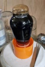
After this and a bit of cleanup with IPA/water mix (Proton 703 has a not unpleasant but very strong smell), a bit of light tappety tapping and gentle manipulation and the base came away practically falling off... wires'n'all 😵 😳🤐
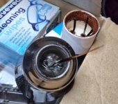
The remains inside were quite heavily corroded, breaking almost all at the same point, but one of them was very close (<1mm or so) from the glass interface, so needed to get a bit creative to make a connection... Although this later turned out to not be the right connection!
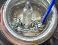
For the other three wires that had about 8mm exposed, a little loop was formed and some ptfe sleeving to help separate (as the loops diameter meant the wires were much closer together):
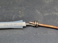
At this point I found (or so I thought) the filament connections (it wasn't possible to see where they went as the wires fell away, and glass is coated inside) as the outer left and right (the very short one above), as they measured continuity when I probed them. The inner two didn't seem connected to anything so thought grid and anode respectively (this was an error - should have cleaned the wires first!).
I used some citric acid, deoxit and gentle scrubbing with a micro pen diamond grinder to make them wettable to solder and make a good connection (easier said than done when working in a fairly deep cavity with a fragile vacuum evacuation tube in the way), and connected what I had thought was filament (but it was now measuring dead short) to the bench supply. On putting 1.5A through them the only thing that got warm were the leads themselves, so something was off.
Due to the black coating on these valves it was very hard to see inside to identify the structure, comparing with another 300B with clear, and plenty of light and trying to see through, it still looked like the outer two wires ran up to the filaments and the 2nd one forked in two looking like the grid.
I did note that the anode wire seemed to have broken away longer than the other 3, so this persisted as a source of confusion - compounded as measurements wouldn't make sense if the very short one was the anode as it had continuity to the left hand wire - until I saw a glimpse of metal at the very very edge of the glass. 🤔
It turns out the outer two wires were not the filament as I measured again (having omitted to do so after cleaning/soldering) - filament was the INNER two wires! The factory must have brought 5 wires through (the grid through twice and trimmed one of them).
Connecting to bench supply and brought up to 5V and they glowed nicely. Phew.
It took a few attempts and gentle grinding at the remnants of that glimpse of metal at the very edge of the glass (there was only around 0.5mmx1.5mm available), including the glass itself (not sure how thick) in order to get enough of a cleaned surface to solder to and managed to get the anode wire set. I certainly did not want to disturb this again as it was electrically sound but mechanically very weak.
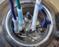
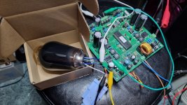
At this point I put on my uTracer and ran a few basic tests, it was alive 😀
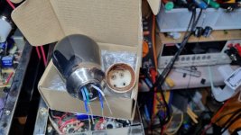
Now to clean up the base a bit, and gently put back in place, I used some clear nail varnish diluted with acetone smeared around the existing glue in the base, gently replacing the base in the same position it was in, and dribbled a bit more acetone around, held with a couple of rubber bands . Hopefully this will secure it well enough, time will tell.
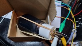
Re-ran the uTracer and got a fair result I think :

So anyway thought I'd share this in case it helps anyone else!
I left the valve in a small cap of the Proton 703 chemical for 24 hours (dissolves various silicone based materials but safe for circuit boards etc so was ok for the gold plated pins, copper etc).

After this and a bit of cleanup with IPA/water mix (Proton 703 has a not unpleasant but very strong smell), a bit of light tappety tapping and gentle manipulation and the base came away practically falling off... wires'n'all 😵 😳🤐

The remains inside were quite heavily corroded, breaking almost all at the same point, but one of them was very close (<1mm or so) from the glass interface, so needed to get a bit creative to make a connection... Although this later turned out to not be the right connection!

For the other three wires that had about 8mm exposed, a little loop was formed and some ptfe sleeving to help separate (as the loops diameter meant the wires were much closer together):

At this point I found (or so I thought) the filament connections (it wasn't possible to see where they went as the wires fell away, and glass is coated inside) as the outer left and right (the very short one above), as they measured continuity when I probed them. The inner two didn't seem connected to anything so thought grid and anode respectively (this was an error - should have cleaned the wires first!).
I used some citric acid, deoxit and gentle scrubbing with a micro pen diamond grinder to make them wettable to solder and make a good connection (easier said than done when working in a fairly deep cavity with a fragile vacuum evacuation tube in the way), and connected what I had thought was filament (but it was now measuring dead short) to the bench supply. On putting 1.5A through them the only thing that got warm were the leads themselves, so something was off.
Due to the black coating on these valves it was very hard to see inside to identify the structure, comparing with another 300B with clear, and plenty of light and trying to see through, it still looked like the outer two wires ran up to the filaments and the 2nd one forked in two looking like the grid.
I did note that the anode wire seemed to have broken away longer than the other 3, so this persisted as a source of confusion - compounded as measurements wouldn't make sense if the very short one was the anode as it had continuity to the left hand wire - until I saw a glimpse of metal at the very very edge of the glass. 🤔
It turns out the outer two wires were not the filament as I measured again (having omitted to do so after cleaning/soldering) - filament was the INNER two wires! The factory must have brought 5 wires through (the grid through twice and trimmed one of them).
Connecting to bench supply and brought up to 5V and they glowed nicely. Phew.
It took a few attempts and gentle grinding at the remnants of that glimpse of metal at the very edge of the glass (there was only around 0.5mmx1.5mm available), including the glass itself (not sure how thick) in order to get enough of a cleaned surface to solder to and managed to get the anode wire set. I certainly did not want to disturb this again as it was electrically sound but mechanically very weak.

At this point I put on my uTracer and ran a few basic tests, it was alive 😀

Now to clean up the base a bit, and gently put back in place, I used some clear nail varnish diluted with acetone smeared around the existing glue in the base, gently replacing the base in the same position it was in, and dribbled a bit more acetone around, held with a couple of rubber bands . Hopefully this will secure it well enough, time will tell.


Re-ran the uTracer and got a fair result I think :

So anyway thought I'd share this in case it helps anyone else!
Last edited:
Just for further info if anyone is interested, below is photo of the anode wire that broke away at the glass (right side portion) - you can see there is a solder connection made (the other 3 wires broke away at this solder point).
Given the verdigris that can be seen I have a feeling that a rather corrosive flux must have been used and not cleaned off during manufacture leading to this issue, exacerbated by the heat involved in operation, drawing in humidity during cooling cycles.

Given the verdigris that can be seen I have a feeling that a rather corrosive flux must have been used and not cleaned off during manufacture leading to this issue, exacerbated by the heat involved in operation, drawing in humidity during cooling cycles.
- Home
- Amplifiers
- Tubes / Valves
- Removing glued base of faulty Shuguang 300B-Z